Für 10 € mit HX711 geht keine Temperaturkompensation. Deshalb machen ja alle billigen Waagen einen automatischen Tara-Abgleich nach dem Einschalten
Na wenn ich den Themenbereich “Wiegen” richtig verstehe misst das Setup entweder nur einen Widerstand (der, der durchs Gewicht verzerrt wird), dann ist sie meinem Verständnis nach nicht temperaturkompensiert oder aber sie misst noch nen Referenzwiderstand, der sich an nem nicht-arbeitenden Teil des Metallstücks befindet und als Temperatur-Referenz-/Kompensationswert genommen wird.
@weef konnte mir das persönlich ganz gut erklären, hier drüben finden sich auch noch Dinge im Forum dazu, wo dieser Aspekt erwähnt wird:
Sonst schließen sich ja noch weitere Fragen an:
- Wie lang ist das Kabel?
- Ist das Kabel geschirmt?
- Welche Farbe hat das Kabel? [1]
- Ist das Kabel der Sonne ausgesetzt?
- Bekommt auch der Metallblock selbst Sonne ab?
Klingt lächerlich, aber der Seebeck-Effekt nimmt auch dort Einfluß. ↩︎
1 Like
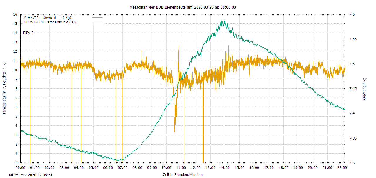
Zum Testen auf dem Schreibtisch habe ich folgendes setting:
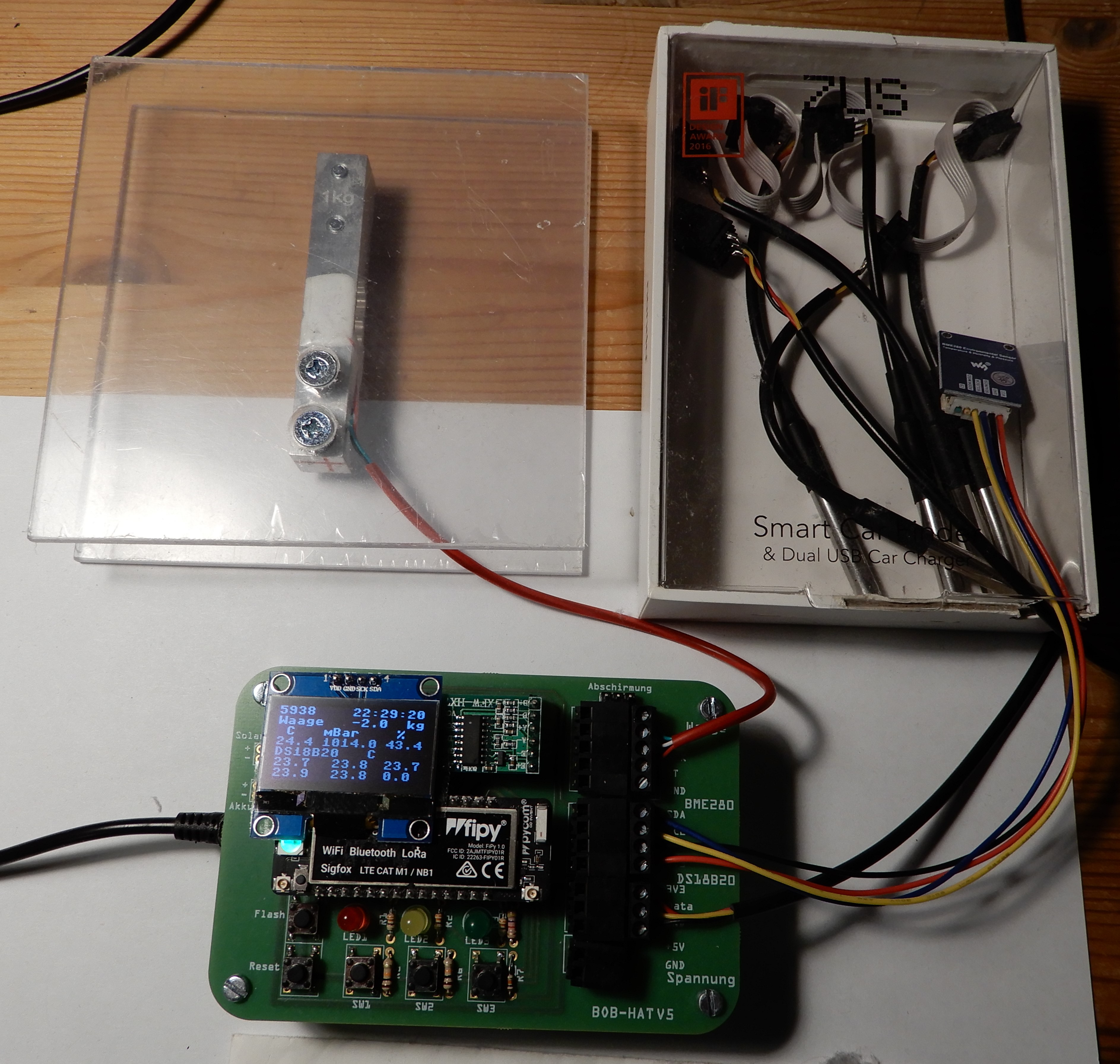
Die China-Wägezelle befindet sich zwischen 2 Plexiglas-Platten und wird zum Testen mit einem 10g-Brief belastet. Die 5 DS18B20 und der BME280 befinden sich in einer Pappbox mit Klarsichtdeckel um Luftstömungen zu reduzieren.
Wenn nun vormittags die Sonne auf das Ganze scheint, verändert sich das angezeigte Gewicht so stark mit der Temperatur.
Die Bosche-Wägezelle ist draussen auf dem Teststand deutlich temperaturstabiler.
Danke füers Bild, ich nehm an die Sonne “flutet” das Setup vollständig? Fände es mal spannend zu sehen, wie stark der Effekt ist, wenn bspw. nur das rote Kabel und nicht Wäageblock und Fipy-Board der Sonne ausgesetzt sind. (Und danach mal das rote Kabel durch nen weißes tauschen).
1 Like
Wenn der Alublock der Waage direkte Sonne (!) abbekommt sind die veränderten Werte eher chaotisch, das ist nochmal etwas anderes als ein Temperaturänderung der kompletten Umgebung!
Wägezelle immer beschatten!! Wenn möglich das Kabel ebenfalls!!
Du wirst ähnliche Effekte bei der Bosche haben, wenn die in der Sonne liegt.
2 Likes
Das oben ist meine Testumgebung auf dem Schreibtisch.
Meine Testbeute mit der Boschezelle sieht so aus:
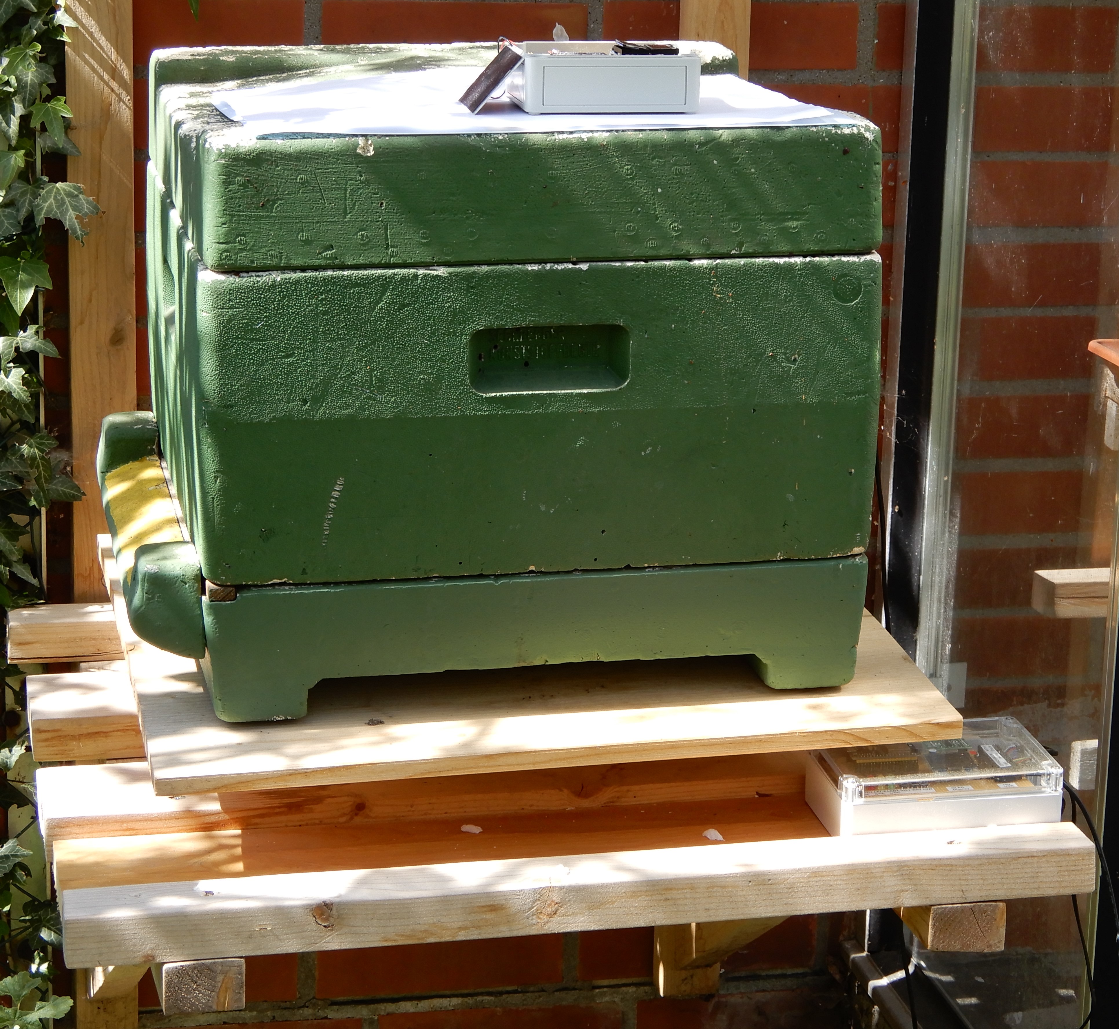
Über dem ganzen ist ein Dach aus Acrylglas. Die Wägezelle liegt immer im Schatten. Seit 6 Wochen steht eine Testwasserkiste mit 10 kg darauf. Die Temperaturabweichung liegt bei 10.0 kg +/- 0.1kg.
1 Like
Das Testsetup deiner Bosche-Zelle ist deutlich besser als das der China-Zelle, ohne direkte Sonne auf Wägezelle und ggf. auch auf das Kabel. Ich denke, wenn du so die China-Zelle testen würdest, wären die Schwankungen geringer / anders als bisher gemessen.
Good thing you noticed. And yes one could expect greater temp dependent deformation of metal in cell with higher temp. But if the basic hive is fairly heavy compated to load variatio (from honey mainly) possibly it doesnt matter that much
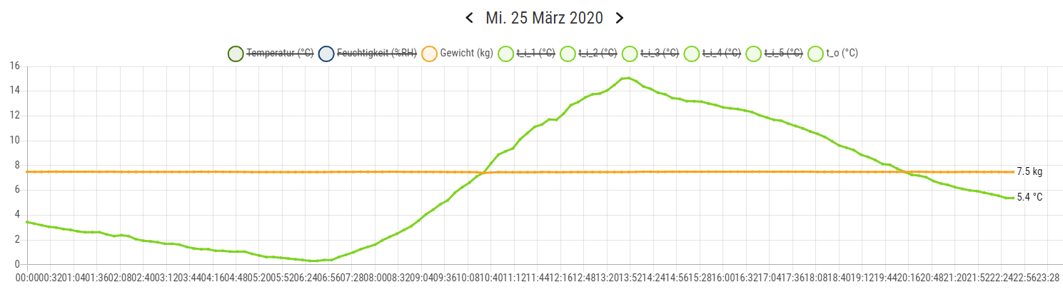
Ein weiteres Beispiel ist die 1kg China-Wägezelle zum Testen auf meinem Schreibtisch:
Da hilft keine Temperatur-Kompensation sondern nur eine bessere Wägezelle von Bosche
Die Wägezelle wurde im AP-Modus auf 10 kg abgeglichen. Hat nicht so ganz funktioniert, aber zum Software testen reicht es.
Keine hardware-basierte, die in den Datenblättern manchmal drinnen steht meinst du? Ansonsten schaut das ja mit fast r = 1 sehr gut zu korreliert und softwaretechnisch könnte man die vermutlich gar nicht so schlecht kompensieren.
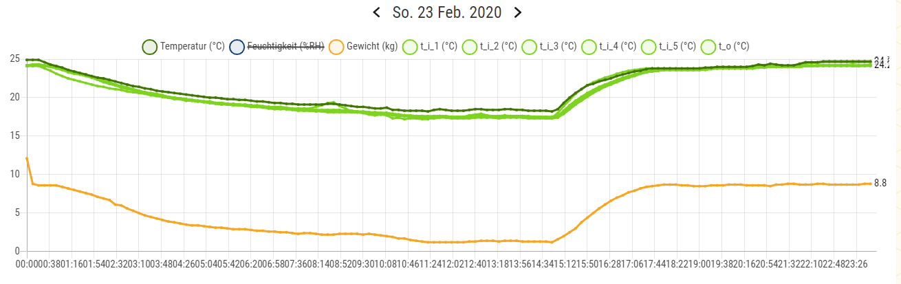
Ich habe die Temperaturdrift der Boschzelle H40A auf der Terrasse bei Nachtfrost untersucht:
Auch in der Vergrösserung sieht das relativ gut aus:
Bei 16000 Messungen gibt es kaum Ausreisser. Auf der Webseite sieht man nichts:
1 Like
Sorry to come back to a topic that has already been discussed quite a lot but I would like to better understand.
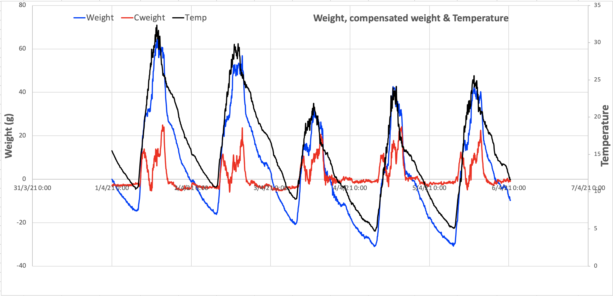
I am using H40 load cells from Bosche. I have calibrated them and i apply a temperature compensation which is a simple linear function of temperature. Below is the graph of what I measure with the best load cell that I have when no load is applied to the scale. See graph below. With temperature compensation, max error is 25g and mean error is 5g (my worse load cell has error ~2.5 higher). I can probably live with that (at least with the best one) but I really don’t understand why I have so much more fluctuations during day time than during night. Initially I thought it was because the load cell was receiving direct sun light but when I make sure the scale is in the shadow, the fluctuations are the same.
Any idea ?
The wiring between the cell and the analog-to-digital-converter (ADC) changes its impedance while its temperature is changes. Try to keep the wire between those as short and as thermal shielded as possible. Looking at the graphs: Is the wire or the cell exposed to the sun during sunset, and less during sunrise?
Makes sense, thank you ! I’ll try to shorten the cables, which are indeed a bit long, partly under the sun and black… I am still puzzled by the fact the fluctuations are up and down (not only in one direction)
You don’t usually have to do that, you will even worse the situation if you ever need to extend them again (see below), even if you save the formerly removed part of the cable. You can also find designs with two 100 Ohms resistors in each wire from the strain gauge to the ADC, so it’s not about ohmic resistance.
If you can ensure the weight scale body is not exposed to sunlight which excludes simple themal expansion of the strain gauge, then you still suffer this:
That’s the key point: partly. What puzzles you, remains being the Seebeck effect.
You are observing the results of a voltage introduced by wires of different materials attached to each other and exposed to a temperature difference. This difference is created when parts of your measurement chain are exposed to different temperatures than other parts - here: e.g. electronics and scale are in shadow, whereas a (unfortunately black!) cable sees light or even sun partly during the day. By thermal conduction, this energy is propagated to the junction of the mentioned metals - and injects these voltages.
Basically it then constitutes a themocouple, that kind of sensors you would use for fast temperature measurements over a wide range. Therefore this unwanted effect is called a ‘parasitic thermocouple’ and it happens on all mounting terminals or solder spots which connect the strain gauge with your ADC. The voltages introduced here are in the same magnitude like the ones you want to measure, that is why you encounter their effect.
To compensate this, it is therefore not only important to record the actual temperature when measuring a ‘reference’ weight, but to also keep any parts from strain gauge to ADC from getting warmer or colder than others:
- if your scale is centered under the hive, it (hopefully) never sees sunlight (or just solar irradiance). But if a part of the cable is exposed to sun, then Mr. Seebeck fools you
- when your sensor node has a solar cell attached to the node’s enclosure and is exposed to sun, it will always have another temperature than (some parts of) the cable and the strain gauge (even without sun), and so have its mounting terminals too - again an unwanted thermocouple.
- … (many other slacknesses which lead to not maintaining same temperature of measurement chain)
Remember that this unwanted voltage is not created along the wire, but only at different material on their contact spots. So reduce the number of materials involved along the chain, but most important: always strive for most uniform temperature.
I’m sure you now can explain this to yourself! :)
I repeat myself when saying that the Seebeck effect and its implications are widely underestimated. Please have a look at those various topics here which repeatedly cover these themes:
- Temperaturkompensation für Waage (Hardware/Firmware)
- Untersuchung und Datensammlung zur Temperaturabhängigkeit des gesamten Wägezellen-Subsystems (this topic)
- Introduction to load cells
- Comparison of Different Load Cells for a 4-Point Scale
- Strain gauge load cell tests in a DIY climate chamber
- Observing weight drift with my setup
- Ausreißer bei den Temperaturwerten, Drift bei den Gewichtswerten
- Analog vs digital signal / gain amplifiers - #6 by weef
- Temperature compensation for HX711 and / or load cell?
- H frame or two bar frames?
and watch how e.g. @thias, @zmaier, @Werner or @freedom2000 have solved this.
If you expose the mentioned metal contact spots to humidity, then you might create another source of voltage: an electrochemical cell… but thats another scope. It is understood to keep away humidity from electronics for various reasons.
6 Likes
Thanks so much to bring me up to speed with this topic. Physics is fascinating and I am happy to have met with Mister Seebeck, even if he makes my life a bit more complicated than expected !
1 Like
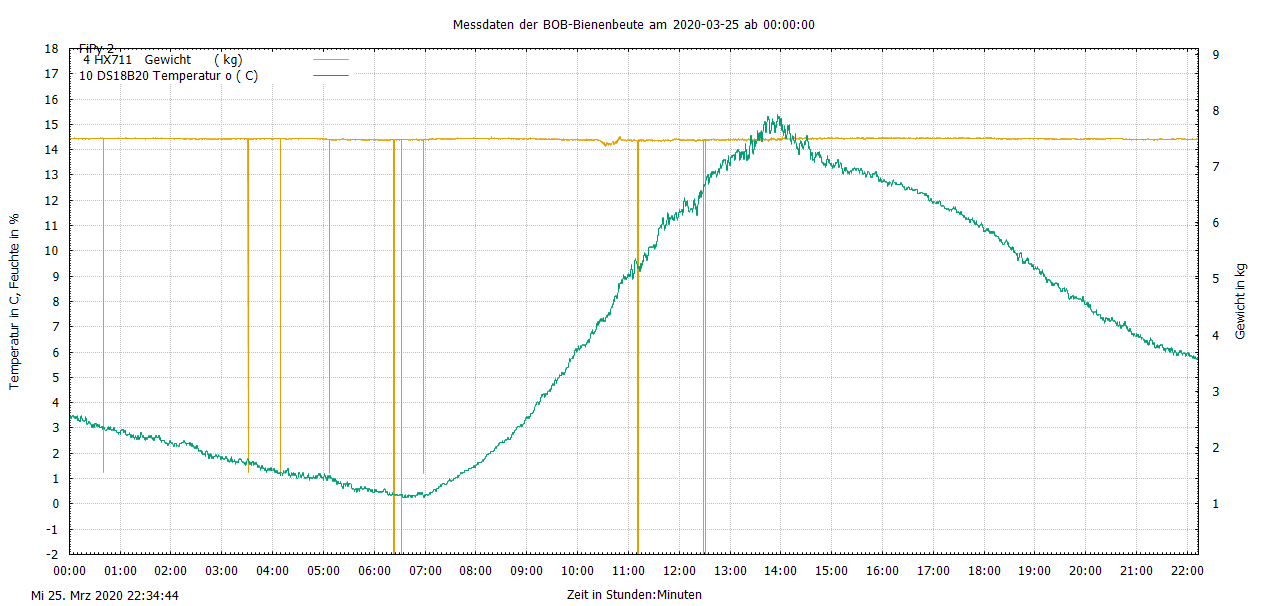
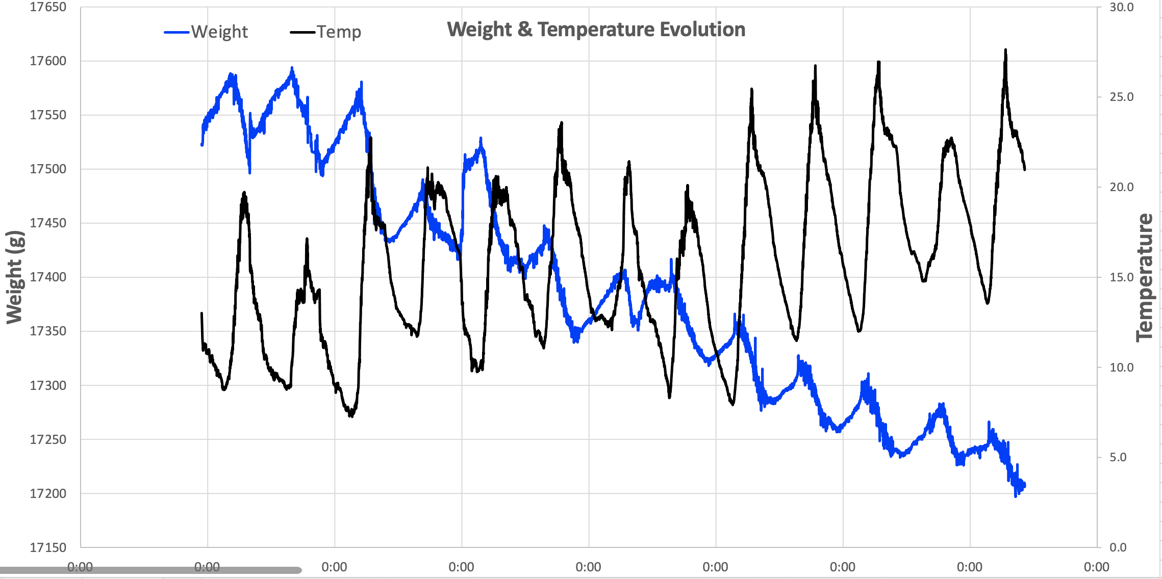
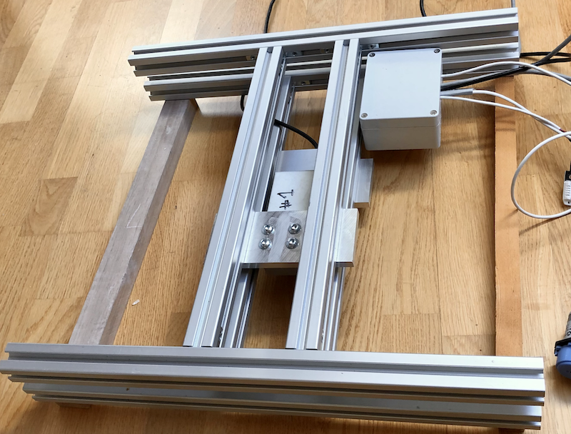
I have been able to resolve the random fluctuations (BTW, avoiding sun on the cables was not enough, it seems the HX711 is not very stable, I had to implement some filters on the HX711 output data) but now I have another problem. As shown on the chart below it seems there is a drift over time. On the chart X axis, “00.00” mark midnight. The load cell is H40-100Kg, the assembly is pictured here below.
Any idea on what’s going on and what the problem is ?
Thanks much !
-Henri
I have asked the question in a detailed email to Bosche and here is the answer that I got from them:
Dear Henri,
thank you for your detailed description. It seems you have collected much more knowledge about load cell in beehives than we have.
Unfortunately, we cannot help with your questions. Sorry.
1 Like
:-)) … seems that too much bekeepers have bothered them with too much questions and too less ordered cells!
I have seen temperature related effects with the Bosche cells but no heavy creep till now, would have expected that a heavy load over a day would perhaps lead so some creep on a new load cell but your observations last over a week. What is on the scale? I had a flower pot on a scale and have seen “nice” descending values over time. Do you have a wet wooden hive on the scale or other meterial that can dry? Any reason for real less weight?