Hi Henri,
I got referred to your load cell temperature compensation post on Hiveeyes, when I was exploring a post considering thermal drift management of load cells in combination with the HX711 ADC at the Arduino Forum.
In your example is shown that your approach reduced the thermal drift of a Bosch HX40 load cell by nearly a factor 8 to only 2 g (1 sigma over a 3 day period) which I think is a very good result indeed. If I understand correct the Bosch HX40 uses 4 strain gages (2 in compression and 2 in tensile mode:Single point load cell H40A | BOSCHE) in a full Wheatstone bridge and as such the load cells response is (partly) temperature compensated.
However, in your application you want to stretch the load cell into a high resolution range where its response shows some remaining temperature dependency in the order of a few g per K. Given the temperature dependency, derived by calibration, and the load cell temperature you should be able to correct for thermal variation improving the measurement resolution of the HX40. In your application you’ve measured the temperature of the environment rather than the load cell itself and you state that the load cell temperature won’t keep up instantly with environmental temperature variations because of its thermal mass and the limited heat-exchange with its environment.
To overcome this, you propose a thermal ‘model’ that estimates the load cell temperature response when it is exposed to a varying environmental temperature. A sophisticated but also elaborate approach used in various high accuracy systems where accuracy is valued above added complexity.
When I analyzed your data-file I was surprised to notice that according to your model the estimated load cell temperature is at most deviating 0.25 deg C from the ambient temperature during an ambient temperature variation of about 10 deg C per 12 hours. In your example the calculating effort to derive the load cells temperature from the ambient temperature variation with the suggested model adds up to a max correction of only 1 g compared to a more simple temperature correction using the ambient temperature.
Only if the ambient temperature variations are steeper or the delay time of the load cell is higher, the additional correction by the model will get significant with respect to your variation-goal of about 2 g. So this questions why to use the elaborate calculations which barely helps to improve the thermal drift correction, and in case it would why don’t put a temperature sensor onto the load cell directly so you obtain the load cells temperature by measurement instead of additional and elaborate calculations?
Despite this, I think, for this case, the thermal correction is quite useful and interesting as it shows to be able to reduce the measurement variation to 2 g (1 sigma over a 3 day period), and if I understand from your LOADCELL_DIVIDER value the measurement range of the H40A was 100 kg, you’ve achieved a noise level of only 20 ppm. This is at least 2-3 orders better as suggested achievable by National Instruments (How Is Temperature Affecting Your Strain Measurement Accuracy? - NI).
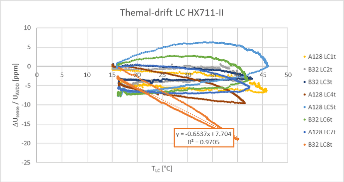
Your post inspired me in trying to extend the measurement range of some cheep halve-bridge load cells but this attempt failed due to higher drift values exceeding the thermal related drift see graph below, and for that I think the Bosch H40A load cells seem more suited.
I hope this may of be of some help for those who want to extend the normal operation range of load cells for their specific applications.
Regards,
Geert
