More on load cell temperature compensation

Hi all,
I found your post after some research about the strange behaviour of load cells.
Your analysis is very intresting.
But, I built a Scale with the economic load cells (GitHub - Slaykristian/ArniUino).
Errors are present and as you studied, there is a conclamated temperature relation.
In particular, I noted that variations depending by the action of value variation (not depending by the Celsius degrees) more that by the own final value.
I’m not an electrical engineer, but a civil engineer… But some of my colleagues that are from the first category, suggest me a solution for the error copensation.
They said that, because load cells are cheapest than yours, I can add 4 load cells with another HX711 and load these by a note weight, i.e. 2kg.
Every 30 min., when a new data read it starts, the scale reads data from the 2kg loaded group of cells, evaluate the difference due by the error, and use this parameter in order to compense the weight reading of the others 4 load cells under the hive.
What do you think about this? It could be a different solution, suitable for more cheap load cells solutions?

Thank you.

Christian

Bonjour Christian,
It’s always interesting to test new approaches but based on the randomness of the errors you get with cheap load cells, I doubt that two sets of such load cells will drift the same way. It you try, please let us know and have fun !
-Henri

I would try to implement a capacitor located on HX711 power input.
I hope to find a compensation of tension variations.
If it will not changes, I’ll try to reinvent the device by using a Bosche H40 cell.

Regards,

Christian

Hi Christian,

I Agree with Henri, the drift-tolerances of these load cells are too poor compared to the expected drift-limit in your application, that it is very likely you’ll end up with a non matching reference-weight drift compared to the beehive-weight drift.

Henri’s tests showed that even the ‘best known’ Single point Bosche H40E load cells, with for me still unknown drift specifications, but my guess having 1 order better drift tolerances as the cheap half-bridge bathroom-scale load cells, have a unique drift sensitivity and as a result these wouldn’t be suitable as a drift-reference without further calibration.
Despite my low expectations the proof is in the testing, which is of course up to you.

If you would go ahead, allow me to suggest to pick best half-bride load cells from a ‘dozen’ by calibration of sensitivity to weight and thermal drift. Best meaning: least deviation in weight sensitivity in combination with low drift sensitive and least deviation in drift behavior.

The benefit of the half-bridge load cells is that you can select the position of the load cells in the Wheatstone-bridge, for which you can compensate the individual load cell drift to obtain a less drift sensitive measurement system compared to the individual load cells.

I’m not a statistical engineer but I can recall that basic normal-distribution statistics suggest it takes a population of 100x to reduce the variation by 1 order so you probably need more like a gross than a dozen load cells to start with (100x 4 = 400 units), which all need to be calibrated on weight- and drift-sensitivity…
So the dilemma is if you’re either better off (in price and time) with the Bosche Single point load cells, or, since you’ll find multiple assembly possibilities, which you can use for other beehives.

Would be nice to read about your decision and progress-learnings.

Best regards,

Geert

Dear all,
At the end I search on this forum and I choose to follow your suggestions.
Maybe I’m wrong and newbie on this forum, but is not so easy to find a consumptive post with all the “strenghtness” and “weakness” of the different load cells.
The derive of the half bridge cells is very bad.
As Henri said, there are a lot of random measurements.
So.
I don’t like the solution with one single point load cell.
I would like to keep the solution with 2 parallel “bars” maybe made with alloy.
I read several post in this forum about czl601 load cells. So, I want to buy 2 pcs. 100kg each . But I don’t find a clear analysis about temperature effect (which says if the effect is high but compensable) and about the arduino solutions with them.

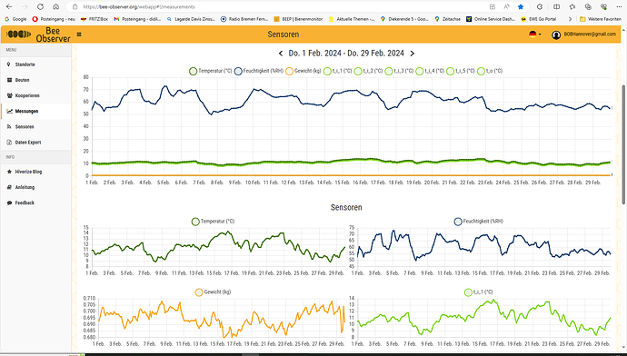
Ich betreibe eine BOB-Waage mit einer Bosche H30A Wägezelle seit 2 Monaten in einem Abstellraum um die Stabilität zu beobachten. Das Licht kommt von einem Nordfenster, die Temperaturschwankungen sind gering, die Feuchtigkeitsschwankungen kommen, wenn ich meine Wäsche zum Trocknen aufhänge oder es regnet.
Im Bild zeige ich die Messwerte vom 1. bis zum 29. Februar.

Die Gewichtsschwankungen ( 30 g ) bei Temperaturschwankung ( 8 °C ) sind so gering, dass es sich meiner Meinung nach nicht lohnt, über komplizierte Temperaturkompensation bei Bienenstöcken ( 30 kg ) nachzudenken.

1 Like

@didilamken, thanks for sharing your one month stability performance of your BOB with Bosche H30A.
@Slaykristian, Also Diedrich, shows a fair month-stability with the Bosche type load cells although I guess the ambient condition variation was reasonably mild compared to real outdoor conditions sure for my ambient in February ;-).

Concerning your ‘doubt’ about what selection criterion to maintain, I think this is indeed an issue and I think also an unexplored area at this forum. This forum presents at least some good performing Bosche Single point load cells, but strangely enough Bosche don’t share any specification on this performance on their website and their technical support either don’t know or play dumb.

Obviously we’re using the Load Cells way beyond their normal operation window wrt to accuracy/stability, so the specification and the one-off experience of Diedrich and Henri might be an indication but is no guarantee that you’ll end up with a stable BOB. As a consequence we have to figure out ourself a way out or accept the variation.

Regards, Geert

PS, I’m about to finish some additional test exploring the strange thermal drift of the half-bridge load cells as summarized in my post above from November last year. I think I have some evidence that the strange non-linearity in the observed thermal-drift is related to dehydration and hydration of the load cells when they are exposed to a thermal cycle to determine the thermal-drift. I’ll share my results on short notice.

Thank you for this answer.

I’m pretty shure that I’ll try with this solution
I would like to buy 2 CZL-601 100kg.

Anyway, as beekeeper, I think that differences of also max +/- 100g on the real weight, are not so big in an enviroment which variates its weight generally in winter so slowly. The real use of theese datas is parallel to understood the behavior during hney harvest, which a significative variation could be more also than 1,5-2kg per day.

My hardware config is made by an arduino uno… That’s is supplied by 5V from a 12V battery charged by a photovoltaic panel.

I think that there are a lot of repentine variation of current and potential during the solar charge that cause some apparently randomized measures. I said “apparently”, because the real thing is that sometime the variation is -1kg and after 30 min, comes back to original values.

Hi Christian,

If your tolerances are less strict you might have reasonable chance getting acceptable drifting single point load cells.
I’m not a beekeeper so I wonder if in winter the hive-weight is not varying that much, wouldn’t you desire for this higher resolution to detect something is going on in the hive…

Wrt the ‘peeks’ spike caused by voltage variation of your power supply: to read you load cells, do you use an ADC which has a voltage regulator on board and performs a ratio metrical measurement (so the Wheatstone response signal relative to the Wheatstone supply voltage)? These ADC should not be (too) sensitive for voltage variation of your power supply. For example the HX711 provides these features but I’m sure there are several alternatives.

Good luck with your project.

Best regards,

Geert

Thanks Geert for your reply.
Generally during the winter, in a good honeybees family, you can observe a normal consumption peak rate of storaged honey which is around 3Kg in late december/january and 2kg for the rest.
When you observe a variation of 1kg in defect, during a single week, you have to check if something bad happened or if the colony is passed away…
Is much more usefull, in order to have an idea of the colony’s health, to have a temperature/humidity sensor inside the hive. I have one for inside datas and one for the outside. The mass of honeybees migrating inside tha hive, sometimes on the right or left or upside or downside … it moves on continuosly. When the core of the colony migrates close to the sensor, the temperature is near to 25°C (with peak of 30°C as well, even if outside you have 0°C or less). When is quite far, temperature is around 21°-22°C. Humidity must be between 50-60% in any case. This is normal for these incredible creatures…
If suddendly these values drift more or less equal to the external datas, that’s could mean “death” or “big damages” on the colony.

About the weight, is much more usefull to reason on the average values variation during a certain interval of time, than a single point value.
So, I think that if you weight an Hive of honeybees, the beekeeper has to learn previously how to understand the datas.
Variations around +/- 0,1kg between 12h are not so relevant and significative.
When you collect datas during an entire day, you have to do some statistics, you can may use Matlab tools (thinkspeak has this feature). But all entire reasoning must be doing by considering the curves of variations between the average values in ex. during 3 days. In this way, you can do your interpreation and plan some eventually activities.

1 Like

Hi Henri and others who may be interested,

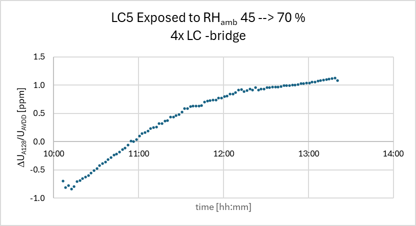
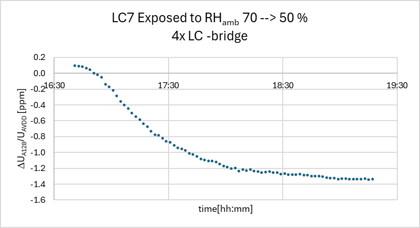
The dissatisfying results of my temperature drift calibration shown in my post above (Nov 1st last year) and your hope to come with a solution to be able to control the creep/drift encouraged me to do some additional tests and I think I have a strong lead the creep/drift I observe is related to ambient humidity affecting the moisture content of the load cells. In a thread started by Gino (Observing weight drift with my setup), Gino came to the same conclusion however, since he was good with the result he seized further investigation on the origin of the creep/drift he observed. In that thread Andreas suggested solder-flux remains in combination with humidity-variation may cause a humidity dependent parasitic ‘short’-circuit between the HX711 pins, resulting in creep/drift at the ADC response. My temperature drift calibration for 8# load cells shows that only for 1 load cell the observed drift seems dominated by temperature, for all others temperature-drift is only a minor fraction of the total observed drift. In my set-up the elevated load cell temperature is realized by placing the load cells on a hot plate which can be heated about 30 degC above ambient in about 90 minutes. The temperature of the load cell is recorded with a thermocouple attached to the metal-housing of the load cell. To be able to measure the response of the half bridge load cell with the HX711 a reference load cell is electrically connected to realize a full Wheatstone bridge. Since the HX711 and this reference load cell are not on the hot-plate, but are exposed to fairly constant ambient conditions (temperature and humidity) during the calibration cycle (total about 180 min) the observed response should be related to the heated load cell, so ruling out ‘short’-cutting solder-flux remains between the HX711 pins (which were also cleaned) as the root cause. On the other hand the drift shown in the graph must somehow be related to the exposure of the thermal cycle! Since heating also affects the moisture content and is therefore a common used drying process. To investigate the load cells sensitivity for humidity it would be desirable to expose the load cell to a dryer ambient without changing the temperature. One way available for me was placing the load cell in a plastic bag containing some Silica Gel (the little bags that are used to control humidity in shipment boxes for electronics). The ambient conditions inside the bag are logged with an wireless Brifit logger which shows that the humidity inside is about 20 % lower compared the ambient outside the bag. The HX711 ADC response to load cell LC7 after placing it inside the bag is shown below:

Or when taking the load cell out of the bag after long term exposure in the bag:

Typical the full response evolves to a few ppm for a variation in RH of about 20 %%, However, it may take hours to reach an equilibrium. Note the load cells are in a 4x load cell Wheatstone-bridge configuration having a load-sensitivity of about 10 ppm/kg → a drift of 100 g for a variation of 20 % RH.

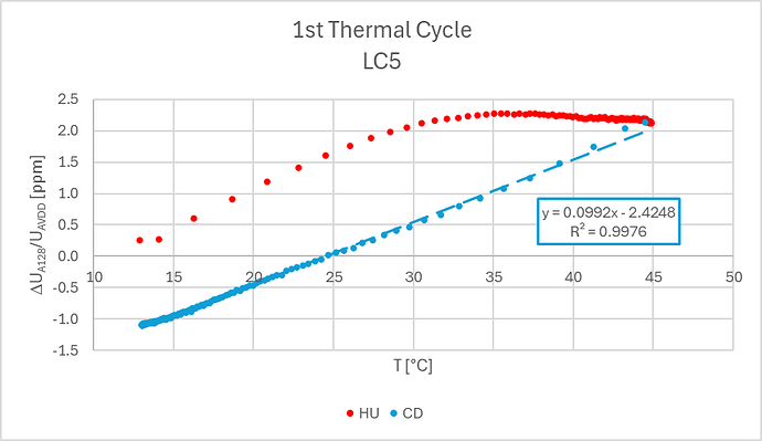
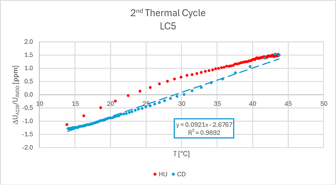
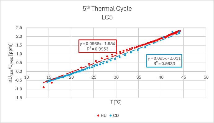
So it seems that the thermal cycle is indeed dehydrating the load cell to a level where its response drifts, and as a result I wondered, when repeating the thermal-cycle, the moister in the load cell comes to a equilibrium and as a result the humidity-drift during the thermal cycle is minimal. So for load cell LC5 inside the bag on top of the Hot-Plate, I repeated the thermal cycle 5x resulting in the following response cycles:


These graphs show for LC5 indeed the humidity-drift is decreasing with each thermal cycle, and after 5 thermal cycles within a period of 30 h, the response evolves to a mainly dominated thermal drift, of about 0.096 ppm/K, and a cycle hysteresis of max 0.3 ppm.

For as far checked, all load cells may show individual drift behavior.

Load cells actually are based on strain gauges and Google-ing on strain-gauges and humidity gives several hits (see Errors and compensations) that describes suppressing humidity sensitivity requires encapsulating the gauges by epoxy or polyurethane type enamel. Apparently the enamel layer is sufficient to meet the specifications but not meeting the bee-hive weighing requirements, and probably Bosche uses a better or thicker sealant.

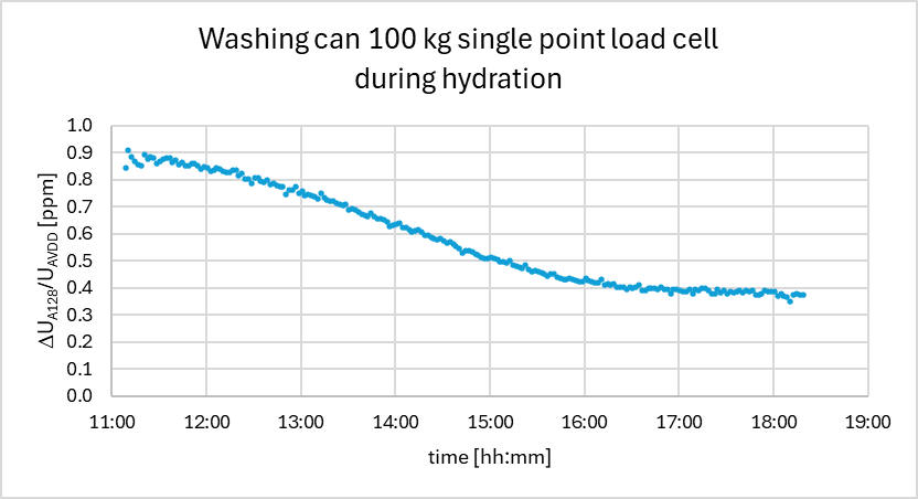
Next to the cheap half scale load cells I also pursued a cheap single point load cell (Washing Can 100 kg) and checkt its humidity sensitivity to 20 % RH variation:

Also this load cell show some humidity-drift in the order of 0.5 ppm per 20 % RH variation. Note the load sensitivity is 20 ppm/kg.

To conclude some approaches to tackle the observed drift:

Since, from measurement point of view, the drift is causing an offset, it would be best to tare-ing the scale mechanically by removing the load. This way all drift-compensations (thermal and humidity) need not to be known in detail and are fully compensated, which I think is the basic method used in industrial scales. However, it is not simple/cheap to remove the load from the load cell to be able to tare the drift out of the measurement.
Since not the hive-weight but the change in weight is at stake here, one could consider to investigate if a balance weighing concept with a course balance feature and a fine-balancing load cell is more appropriate here. In this way the fine-balancing load cell will not need this high drift-specifications as for the scale, so the load cell is used well within its specification.
Finally the humidity sensitivity might be reduced by additional encapsulation or controlling humidity variation (load cell in enclosed environment with silica gel…). But this still will require thermal drift compensation.

Best regards,

Geert

3 Likes

Interesting numbers Geert / @GeHan, many thanks for the investigation! The Bosche H30 for instance is IP65 rated, so I always thought that humidity could not be any issue, in case the wire connection is protected and not “open”. Just for the records, full bridge load cell was …?

Hi Clemens,

The IPxy code, or Ingress Protection code, indicates how well the inside of en enclosure is protected against dust (index x) and water in liquid phase (index y). IPx5 code ensures:

image

Strain gauges and their adhesive seem to be hygroscopic for which they exchange water-molecules (gas phase) with the ambient-air to swell/shrink to an extend where they create a mechanical load on the strain gauges, see HBKworld site:

But the varying moisture content may also lead to a varying parasitic short-circuit of the strain gauge: see link.

The capacity to exchange water molecules with its environment is suppress by a sealant but only to an extend that the creep/drift meets the load cells’ specification which is at least 1 order less stringent as the requirement for some Hiveeyes to limit the creep/drift below 100 g on a 100 kg load for over a period of 1 month!! So my guess is the required Ingress Protection to fulfill this requirement is well beyond IP65. Nevertheless, since Bosche provides one of the most stable load cells, they may have a superior sealant or sealant design.
HBK offers a strain gauge sealant (55 Euro for 30 ml, sufficient for 250x gauges, I assume 50x load cells), but it is unclear if this sealant is sufficient effective to meet the above requirements.

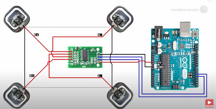
The results presented last November were recorded with a Wheatstone bridge containing 2x half bridge 50 kg cheap bath-room scale load cells in parallel, and the later presented results were recorded with a Wheatstone bridge containing 4x half bridge 50 kg cheap bath-room scale load cells configured according:

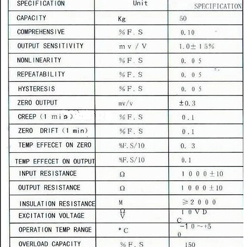
They are so cheap they don’t have a name or type indication but unlike the Bosche load cells they came with a specification sheet:

The 100 kg Single Point load cell was … first of all cheap (16 Euro) secondly Chinese : type ff634, manufactured by Leinggg and sold by Wascan at amazon: Wascan, gewichtssensor, 100 kg parallelle straalweegschaal sensor voor elektronische weegcellen met hoge precisie voor elektronische weegschaal : Amazon.nl: Zakelijk, industrie & wetenschap

Regards,

Geert

1 Like

In case the photo on amazon is one from a sold load cell, it seems it is a CZL601AC we have discussed on some places here at hiveeyes:

2024-03-30 13_58_05-614+kibDpmL.AC_SL1001.jpg (JPEG-Grafik, 1001 × 1001 Pixel) – Mozilla Firefox

Along this CZL601AC datasheet the CZL601AC is IP65 rated. You can find empirical temperature and weight data from some user in Beelogger-Waage mit 2 Wägezellen - #26 by clemens and Temperaturkompensation für Waage (Hardware/Firmware) - #7 by Werner

Hi Clemens,

Indeed it is the same type and thus no need to investigate this load cell deeper. Thanks for making the connection and the link to other posts.

However, I’m afraid the IP65 rating only covers waterproof from liquid phase, and not for water vapour. For sure the speciment I’ve, shows to be sensitive to humidity fluctuations in the ambient air and would not be surprised this also holds for many other types. The observed effect is within the drift-specifications but we desire better/stringent.

Hi Henri and others,

I’m happy to introduce a weighing procedure which compensates/reduces a manyfold of drift factors observed with cheap bathroom scale load cells, which, wrt drift-reduction, even surpasses your Temperature compensation results presented above, with the superior Bosche load cells.
As I presented above my bathroom scale load cells show complex drift patterns over time related to ambient changes in temperature, humidity or other unknown origin.
In my contribution to a topic started by Clemens related to Thermal drift, I showed that Source Voltage modulation of the Wheatstone-bridge is able to reduce for the Seebeck drift which might be incorporated in your measurement circuit design, and given the good results, I suggested to investigate the load modulations to eliminate all drift/creep components, including the Seebeck-drift.
I’ve found a way to modulate the load on the load cells and have good results with long-term stability with a standard deviation in the order of a few g over a period of half a day, while the load cells show drift levels in the order of 50 - 100 g over this period.

Load Modulation
The idea is to alternately load and unload the load cells with the object to be weighed, while the HX711 is logged on both conditions.
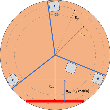
For that I’ve made a setup as sketched below.

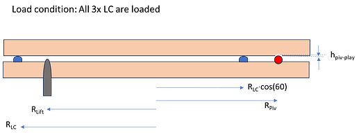
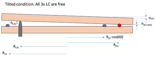
4x cheap half bridge load cells are configured into 1 single Wheatstone-bridge. These load cells are mounted on a disk-shape base plate with 3x load cell pointing upwards and one is hanging in a pocket inside the base plate. A plateau plate is placed on top of the 3x load cells contact-points and the object to be weighed can be place on top of this plateau.
I’ve chosen for only 3 contact points:

  • Due to overdetermined mechanical conditions, 4 contact-points would lead to flatness requirements superior to my machining skills :wink:. As a result this would probably lead to only a situation where only 3 load cells make contact with the plateau and the chance of instable plateau wip-wapping between 2 load cells. Choosing for a 3 contact-point will give a stable contact by definition, regardless of the flatness, and by a triangular configuration this would be reasonable stable for little off center positioning of the object.

  • After individual calibration of each load cell there were only 3# load cells with comparable load-sensitivity (better 0.1 %). Since from the Wheatstone-bridge response you cannot derive how much each load cell contributes to the sum of the total weight, all load cells need to have more or less the same load-calibration, otherwise the result will largely depend on the position of the object on the plateau.

Now to enable the unloading of the load cells there is a lifting-pin (grey) which can be shift upwards by a Servo-motor. When the lifting-pin is touching the plateau the plateau will tilt to the other side un-loading the load cell which is situated to the left of the lifting-pin (see sketch). Raising the lift-pin further will tilt the plateau until it touches a red support-bar which is fixed on the base-plate, after which the 2 other load cells positioned on the right from the lifting-pin will be un-loaded.

With the right dimensional choices this can be realized by raising the lift-pin only a few mm and, since the support-bar will carry half of the plateau load, only half of the plateau-load for the Servo. Furthermore, the tilt-angle can remain under 1 deg to prevent slipping of the object from the plateau (and I think almost no disturbance for the bees to notice).
I’ve found a high torque servo (40 kg*cm about 20 Euro) which can be controlled by Arduino-code.

Load Modulation Results
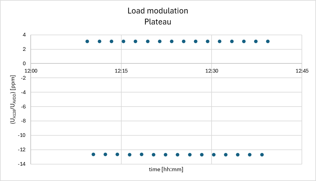
The HX711 ADC response of the Load Modulation at a frequency of 30x per hour looks like the graph below:

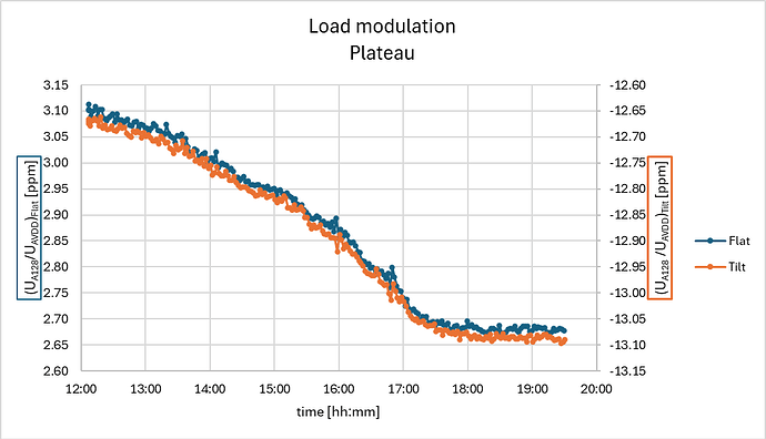
The upper data-points are with the load on the load cells (here only the load of the 1.46 kg plateau), and the lower data-points with the tilted plateau and thus un-loaded load cells. Zooming in in the range at both conditions for a longer period of time the drift of the load cell becomes clearly visible:

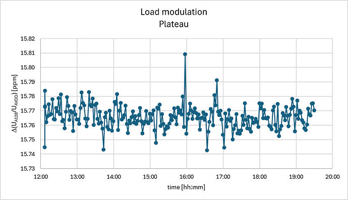
In the graph above the ADC-response of the loaded condition is given by the blue dots corresponding to the left y-axis and the orange dots for the un-loaded condition corresponding to the right y-axis, both having the same range-width. This clearly shows that over 5 h time the 4x load cell drifts over -0.4 ppm (about -40 g), but this is nearly the same for both the loaded and the un-loaded condition. Deriving the difference on ADC-response for both conditions over this period gives:

This gives a constant result with no drift but more or less random noise in the order of 0.01 ppm which is 2-3x the short-term noise I get from my ADC reading, and given the load-sensitivity of 10.8 ppm/kg this is in the order of 1 g.

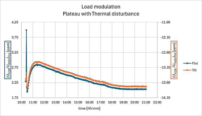
Now let’s increase the load cell drift by exposing 1 of the load cells to a hot air stream from a paint-stripper for app 1 minute:

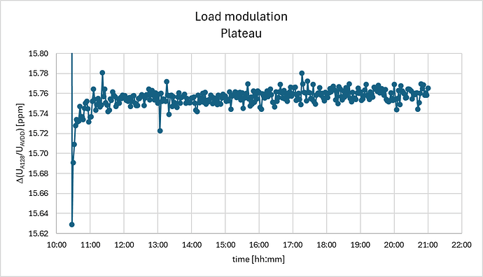
Apart from the temperature rise this thermal-excitation also affects the hydration of the load cell which takes much longer to recover and sums up to a drift of almost +1 ppm (100 g) in the first hour, after which it takes 6 h to recover. But again the loaded and un-loaded response show the same drift and the difference appears only mildly drifting in the order of 0.05 ppm or 5 g in the first half hour and later on app 0.01 ppm (1 g) over 10 h:

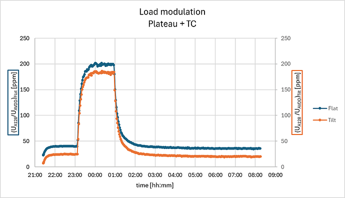
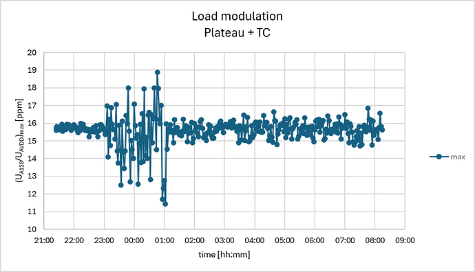
And now for the extreme case when the set-up is corrupted with a thermocouple which is exposed to a temperature cycle (load cells are exposed to ambient drift conditions):

Here the drift is 150 ppm (15 kg) in 1 hour, and again almost equal for both the loaded and un-loaded condition, resulting in the difference signal:

The drift-trend cancels out quite ok, but there is a 10x increase of more random noise (order of 10 g), partly due to noise increase on the ADC reading probably picked up by the thermocouple.

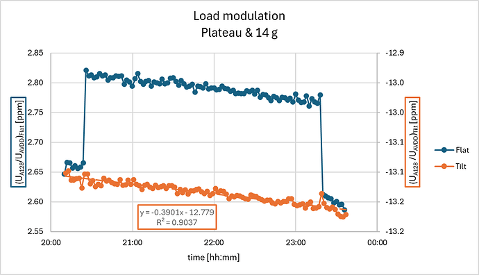
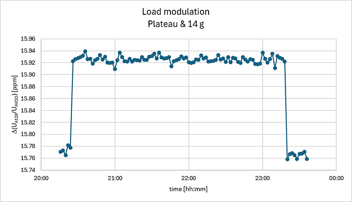
Finally I’ve placed an object of only 14 g for almost 3 h on the plateau while the load cells are drifting:

Here the drift is about -0.4 ppm/day and the placing and removal of the object is noticeable but would be exceeded by the drift in half a day. Again here the difference signal cancels the drift and reveals much clearer the load of the 14 g object:

Concluding
The above results show that load modulation has a substantial contribution in reducing the load cell drift that is affecting the weight measurement, enabling the use of cheap bath room scale load cells for high resolution hive-monitoring. Here, at best, 1 g noise at 150 kg range was realized, which is an improvement of at least 1 - 2 orders.
High loads (> 10 kg) were not tested yet, as my set-up requires some mechanical modifications to make robust load modulations possible. Never the less, I have good hope load modulation will also have high potential to compensate for the assumed creep related to deformation to a continues and high load, as the modulation frequency is sufficiently high compared to the time scale where this creep takes place, as long as the load-sensitivity remains linear and is not affected by this deformation-creep.

The lifting design needs more attention to make it sufficient robust to remain operational for long time under more extreme outdoor conditions. Furthermore, the off-grid application of load modulation will require higher battery capacity and energy source to power the tilting-servo. If all this additional effort is compensated by the load cell’s cost reduction may be questioned, for sure if you can accept some drift. However, if your application requires extra resolution, load modulation might be a valuable option.
It is not as sophisticated as Henri’s temperature compensation method but it is capable to eliminate many more drift-sources
4 Likes

Hi Geert !
Very nice work, congratulations for your creativity !
If I happen to need such high precision with low cost load cells (probably not for bee hives) I’ll think about your way of doing.

Hi Henri,

Thanks for your reply.
Just curios what makes my solution unattractive for bee hives?
Since it was your remark (and Clemens comment, see below) that encouraged me to investigate and share this option, and of course the wed winter season!

Regards,

Geert

this is the “jumping dot”. i think many of us are waiting for further tests to turn hope into knowledge. many of us have our old bathroom scales from back in the days burried somewhere back in the garage.

Sorry Geert, I didn’t mean that your solution is unattractive for bee hives. I haven’t dug into the details of your solution but I found your idea very creative and worth considering for beehives if you find a servo motor that is not more expensive than the high quality load cell (and if energy is available in the apiary)