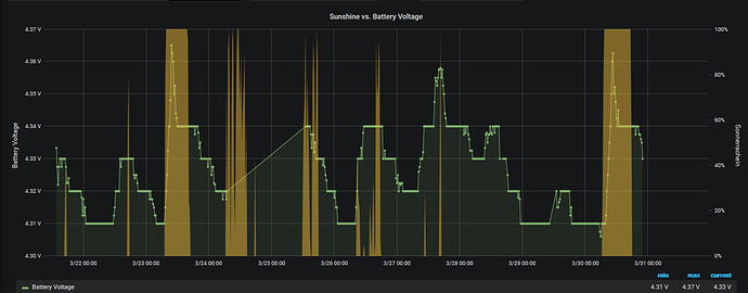
This is a hive monitoring system based on the Adafruit HUZZAH, based on an ESP8266.
The Adafruit HUZZAH we are using is NOT the Adafruit Feather HUZZAH, the Feather uses an USB port, so it will consume more energy. Also, the LiPo charger on the Feather can NOT operate on solar cell, so we have chosen the Adafruit HUZZAH as it better fits our needs.
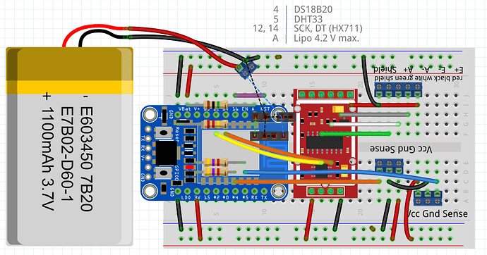
This ist the bread board view (without solar charger):
We have as parts:
- Adafruit HUZZAH with ESP8266 as MC
- HX711 breakout as load cell amplifier and ADC
- two resistors (2x 4.7 kΩ) for the sensors (DHTxx and DS18B20)
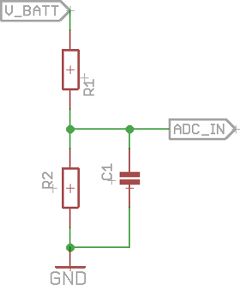
- two resistors (2 MΩ, 10 MΩ) as voltage divider to measure the battery drain (new values in version 0.1.9)
- resistors 10k to pullup GPIO0 and avoid dimming of the onbard LED (new in version 0.1.9)
- 100 nF capacitor in parallel to the lower resistor of the voltage divider to measure battery is recommended (this was not prepared on the first PCB but now done in version 0.1.9
- screw terminals (3.5mm Beinabstand) 3x 3 pin, 1x 2 pin (2 pin + 3 pin for the load cell connector)
- optional for solar charging: for the PCB we need also a CN3065 breakout, this is the solar charging IC (not provided in the bread board version)
- custom PCB
– esp8266-hx711-ds18b20-dht33_pcb_v0.7.fzz (65.4 KB)
– esp8266-hx711-ds18b20-dht33_pcb_v0.9.fzz (68.0 KB)
- as sensors
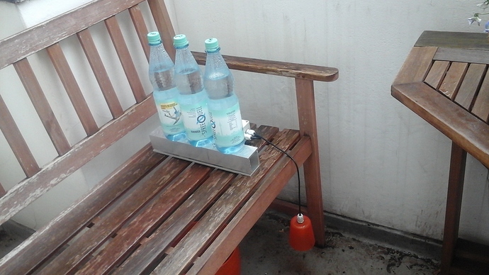
– DHTxx, DS18B20, load cell
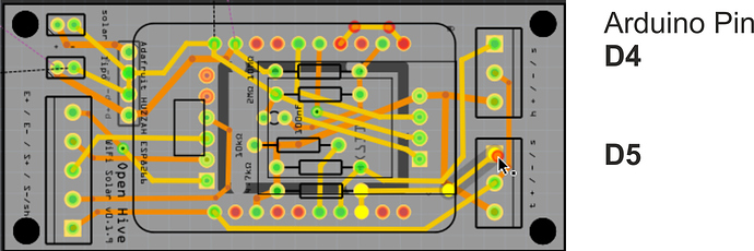
The PCB layout
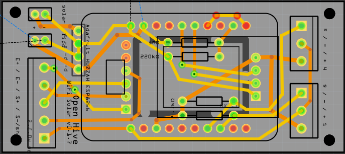
For assembling start with the PCB
Solder the four resistors in place …
… and add a 100 nF in parallel to the lower one:
Add the pin header on the HX711 breakout and cut them (I do it normally before soldering it on the breakout) so that the board on the other side fits also. This is the length without cutting:
Solder the HX711 on the PCB!
Double check the side! Otherwise you have to crash it. ;-)
Now you could solder the header pins for the solar charging breakout. But solder only the pins, not the breakout itself!
Solder the FTDI pins on the Huzzah. Do not forget this before mountig it on the PCB. After this step you can solder the Huzzah in place, be aware of the orientation! FTDI has to be on the load cell screw terminal side.
Now you can fix the JST for LiPo and solar first. Then you should solder the screw terminals.
Finally put the charging breakout in place. It’s a good idea to de-solder the charge indicator LED. It’s useless burned power and we need no lightning in the bee hive.
In the first version place was a bit tight so the sensor’s screw terminals are not aligned properly. But this is fixed in the current version.
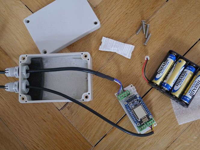
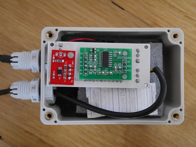
A version with battery power (4x AA ~ 6 V).
