Open Hive WiFi Solar / Adafruit HUZZAH

This is a hive monitoring system based on the Adafruit HUZZAH, based on an ESP8266.

The Adafruit HUZZAH we are using is NOT the Adafruit Feather HUZZAH, the Feather uses an USB port, so it will consume more energy. Also, the LiPo charger on the Feather can NOT operate on solar cell, so we have chosen the Adafruit HUZZAH as it better fits our needs.

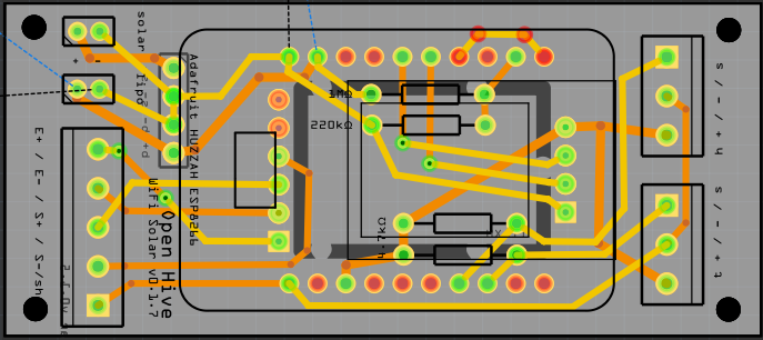
This ist the bread board view (without solar charger):
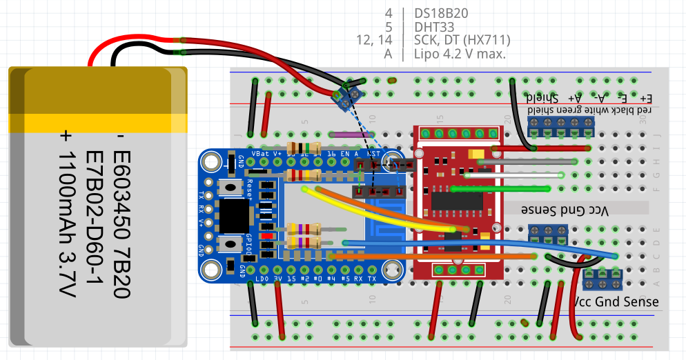
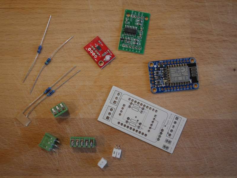
We have as parts:

  • Adafruit HUZZAH with ESP8266 as MC
  • HX711 breakout as load cell amplifier and ADC
  • two resistors (2x 4.7 kΩ) for the sensors (DHTxx and DS18B20)
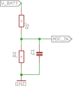
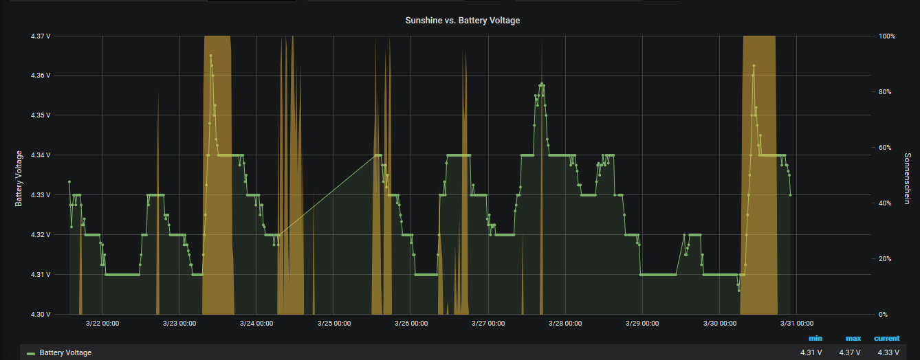
  • two resistors (2 MΩ, 10 MΩ) as voltage divider to measure the battery drain (new values in version 0.1.9)
  • resistors 10k to pullup GPIO0 and avoid dimming of the onbard LED (new in version 0.1.9)
  • 100 nF capacitor in parallel to the lower resistor of the voltage divider to measure battery is recommended (this was not prepared on the first PCB but now done in version 0.1.9
  • screw terminals (3.5mm Beinabstand) 3x 3 pin, 1x 2 pin (2 pin + 3 pin for the load cell connector)
  • optional for solar charging: for the PCB we need also a CN3065 breakout, this is the solar charging IC (not provided in the bread board version)
  • custom PCB
    esp8266-hx711-ds18b20-dht33_pcb_v0.7.fzz (65.4 KB)
    esp8266-hx711-ds18b20-dht33_pcb_v0.9.fzz (68.0 KB)
  • as sensors
    – DHTxx, DS18B20, load cell
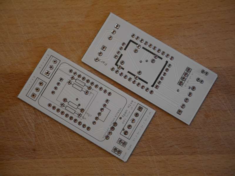
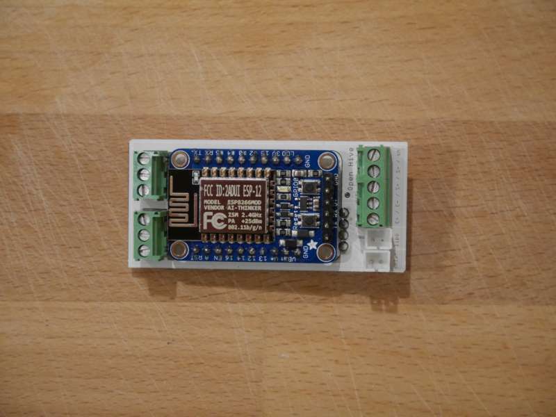
The PCB layout

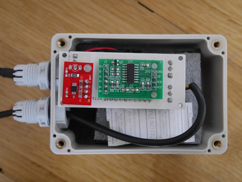
For assembling start with the PCB

Solder the four resistors in place …

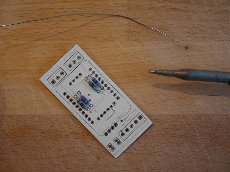
… and add a 100 nF in parallel to the lower one:

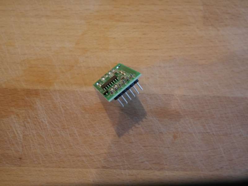
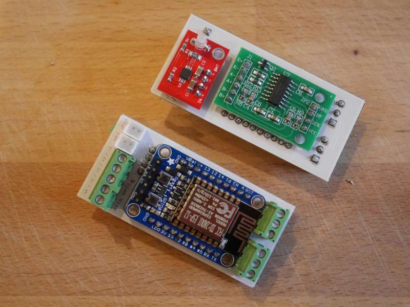
Add the pin header on the HX711 breakout and cut them (I do it normally before soldering it on the breakout) so that the board on the other side fits also. This is the length without cutting:

Solder the HX711 on the PCB!

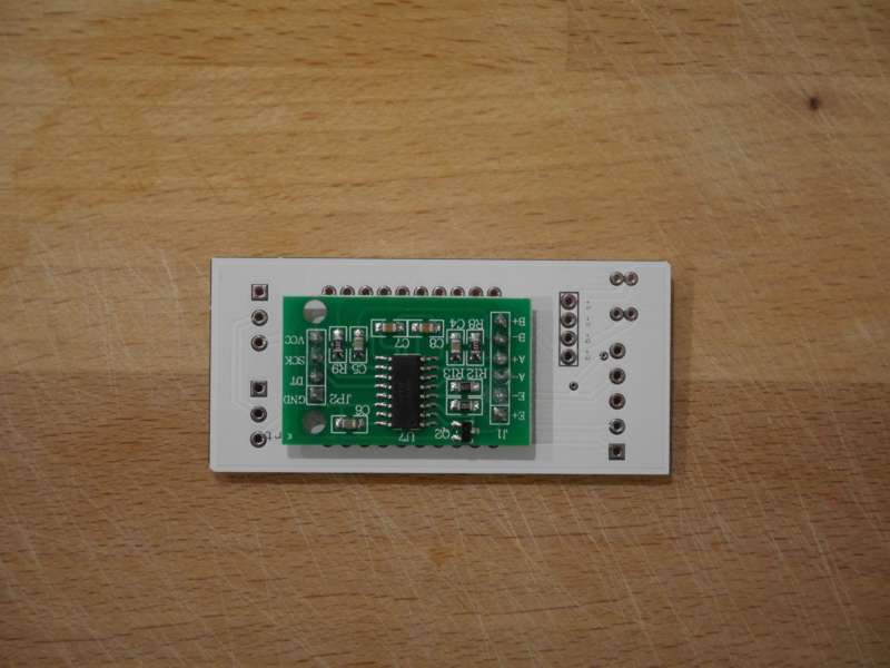
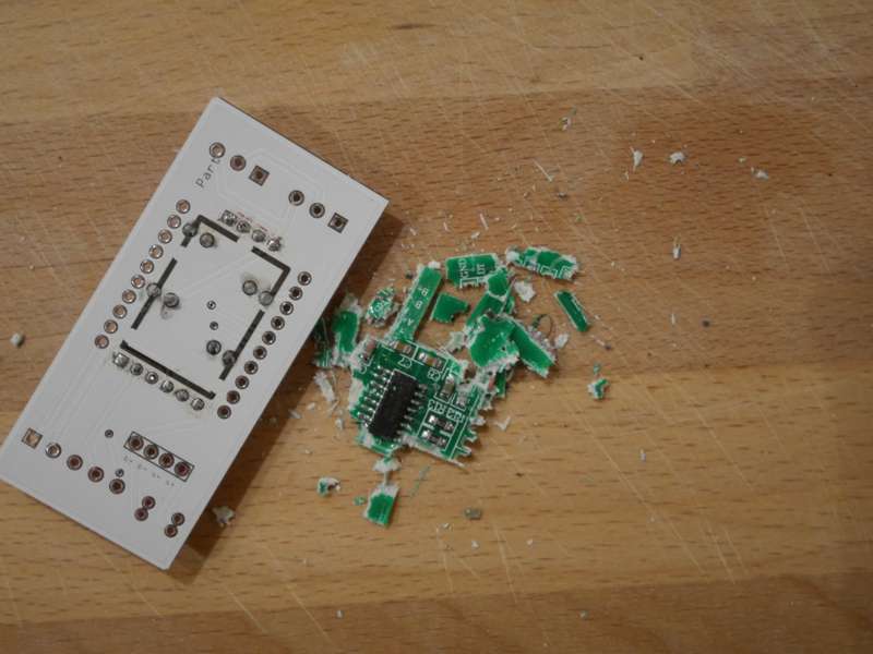
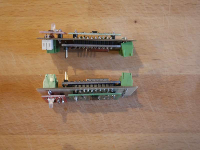
Double check the side! Otherwise you have to crash it. ;-)

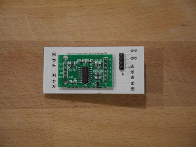
Now you could solder the header pins for the solar charging breakout. But solder only the pins, not the breakout itself!

Solder the FTDI pins on the Huzzah. Do not forget this before mountig it on the PCB. After this step you can solder the Huzzah in place, be aware of the orientation! FTDI has to be on the load cell screw terminal side.

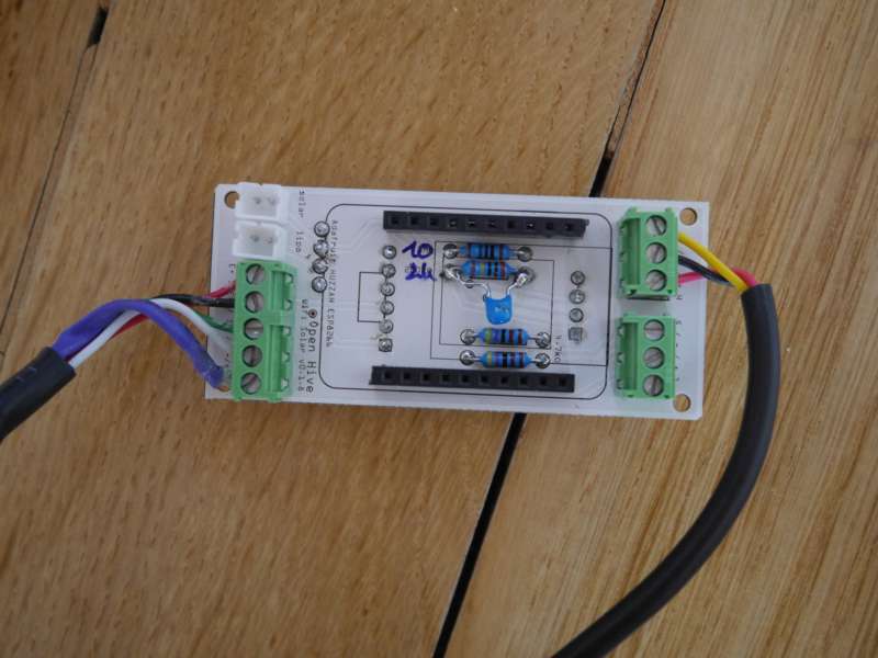
Now you can fix the JST for LiPo and solar first. Then you should solder the screw terminals.

Finally put the charging breakout in place. It’s a good idea to de-solder the charge indicator LED. It’s useless burned power and we need no lightning in the bee hive.

In the first version place was a bit tight so the sensor’s screw terminals are not aligned properly. But this is fixed in the current version.

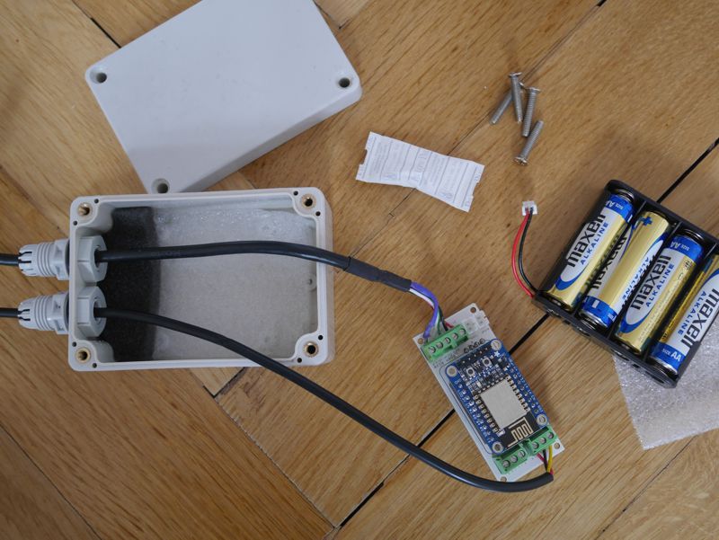
A version with battery power (4x AA ~ 6 V).

3 Likes

6 Monate Laufzeit mit 4x 1,5V-AA-Batterien

Mein batteriebetriebenes ESP8266-Testsystem auf dem Balkon läuft nun schon seit Anfang Februar und sendet ca. 1x pro Stunde Daten an den Server: http://open-hive.org/apiary/test01/node001.html Aktuell sind es 4724 Datensätze seit Februar. Der Zweck war neben dem Austesten der Batterielaufzeit auch “Temperaturkompensation für Waage nötig? Datensammlung”.

Die Batteriespannung im Diagramm schaut etwas komisch aus, da ich zwar den Solarregler schon drangebaut habe ihn aber nicht nutze, ausserdem sind die Widerstandswerte des voltage dividers nicht optimal gewählt. Ein zusätzlich verbauter Kondensator - da wo die Spannung wieder rauf geht - hat auch nichts gebracht. Allerdings schauen andere Testsysteme besser bei den Stromschwankungen aus, vielleicht irgendwas beim Löten versaut, aber oben schaut das eigentlich ok aus.

Die Stromversorgung läuft über 4x AA-Batterien. Nun geht langsam der Saft aus…

… und es gibt erste Aufälle des DHT - interessanterweise ist der DHT immer ein guter Kandidat um Strom-Engpässe zu bemerken, die Waage und auch meist ein DS18B20 laufen noch, der DHT macht aber schon Zicken. Das ist noch ein DHT ohne Kondensator auf der Sensor-Seite, die neue Serie hat einen 1 uF vielleicht würde es mit dem auch jetzt noch besser laufen.

Man kann den ESP nicht so einfach von 1 Stunde auf 24 Stunden Schlaf umstellen, da die maximale Schlafzeit ca. eine Stunde ist, es gibt da ein paar Tricks, wie es dennoch funktioniert. Ich denke damit wären auch Laufzeiten von einem Jahr mit den gleichen Batterien möglich.

1 Like

Nun sind die Batterien endgültig leer. Als finales Update zur Laufzeit mit 4x 1,5V-AA-Batterien

  • Start: 7. Februar 2017
  • Ende: 14. September 2017

Damit kommen wir auf 219 Tage mit dem aktuellen Setup und billigen AA-Batterien. Wir hatten in der Zeit

  • 5404 updates insgesamt, das sind 24,7 update pro Tag (damit könnte man die interne Uhr des ESP etwas nachstelen, sollten ja eigentlich bei 60 Minuten 23 pro Tag sein)

Habe heute die Batterien erneuert, die billigen Maxell LR6 Alkaline-Batterie sind echt Schrott, eine der vier war ausgelaufen, eine zusammengebrochen, hatte negative Spannung und die anderen zwei eine Restspannung von etwa 0,9 V. Die Kontakte der Batteriehalterung war bei der ausgelaufenen Batterie oxidiert, habe sie abgekratzt, scheint momentan zu funktionieren. Start ist also der 1. Oktober, mal schauen, wie lange die Varta-Batterien jetzt durchhalten, bis Mitte Mai? Mit dem Winter werden wir vermutlich kürzere Zeiten bekommen als im Frühling / Sommer.

There is a nice overview from Andreas Spiess for the used CN3065 charging chip:

3 posts were split to a new topic: Rost, Verschleiß, Ersatz

3 posts were merged into an existing topic: Probleme mit der Firmware zur Justierung der Waage auf ESP8266

Mal schnell Batterien wechseln

Wenn ein Text so anfängt, ahnt man schon nichts gute, weil ein Batteriwechsel an sich nichts wirklich erwähnenswertes ist. ;-) Aber von Anfang an: Unser Selbsttest-System hat gut funktioniert. Auch ohne in die Daten zu schauen gab es eininige Warnungen per E-Mail, die indirekt das Ende der Batterien signalisierten, siehe dieses Posting dazu:

Die 4x AA-Zellen haben von Anfang Oktober 2017 bis fast Ende April 2018, also 7 Monate gereicht und das im Winter! Der Datenupload war wie bisher auch stündlich, dabei wurden 5217 Datensätze per WLAN übertragen.

Nun zu den Problemen: Die Schrauben oben waren am Kopf verrostet. Dieses mal musste ich drei verschiedene Kreuzschlitz-Schraubendreher verwenden um noch etwas “Griff” zu haben und die Schrauben herausgedreht zu bekommen. Ein Tausch ist hier demnächst auf jeden Fall fällig, sonst bekommt man die irgendwan gar nicht mehr raus. Die Ecken des Kreuzes sind deutlich verrostet.

Dann ist mir noch ein Malheur beim Einbau der getauschent Batterien passiert. Beim selbst gecrimpten JST-Stecker ist ein Kontakt rausgerutscht und hat ein Kurzschluss verursacht, habe es erst nach ein paar Sekunden gemerkt als die Drähte des Batteriehalters schon warm geworden sind und auch etwas gerochen haben. Nun ist erst mal eine LiPo drinnen, der hat 1200 mAh, mal schauen, wie lange der hält.

New PCB version:

Dimming LED in Sleep Mode

Due to the electronic design of the Huzzah the red LED dimmed light in sleep mode. So I desoldered / destroyed the LED to save power on the boards.

Some people hesitate to cut traces or “destroy something”. As an alternative you can add an 10k pullup to GPIO0, see: Adafruit HUZZAH red led behavior under deep sleep - Everything ESP8266

More information in the Adafruit Forum:

Smooth battery monitoring

Changed voltage divider for measuring battery power to 2 M / 10 M to save power. And added a 100 nF capacitor in parallel to the voltage divider’s 2 M resistor to smooth output.

Didn’t get it where 2M and 10M are and hence this cap is, as I don’t know your V_batt, Your source appears to be a 1S LiPo, then you might have R1=2M and R2=10M, but however the cap must be wired this way:

image

this can get a noisy measurement (0,33 µA ground current @4V), use good oversampling, averaging…

In the ESP datasheet they don’t state the input impedance of the ADC inputs: some people apply the input leakage (5nA) of an EPS’s GPIO pin also to the ADC in, others claim “in the range 1M”. This has implications on your divider as it might deliver too few current for the ADCin for even 10bit resolution and veeery slow sampling rate - it must be reviewed.


Time to have another GPIO pin controlling a BJT or FET to power a divider w/ more reasonable resistance values?! ;) Then you have the divider only powered when V_batt needs to be measured, and you can measure faster events in voltage changes (for power analysis of e.g. different “up” states).

Yes, I have a 1S LiPo as source but tried a 4x 1,5 V AA battery pack with ~6 V also. And the position of the resistors and the cap in the same position as you mentioned, thanks! The resistor and cap values are the same as in the Seeeduino Stalker’s voltage divider.

Btw I measured – without anything sensors or the voltage divider – a current of 0.08 mA in sleep mode. It was slight lower (~0.07 mA) with the 10k pullup on GPIO0 to avoid the dimming LED:

Mini-CheatSheet

Im Herbst schwächeln meine 0,5-W-Solar-Zellen ja etwas, aber momentan laufen die trotz 5-Minuten-Update bei einer Test-Installation für das Statista-Projekt am ZK/U überraschend gut!

1 Like

Gerade mal nachgemessen: Der Stromverbrauch im deep sleep liegt bei ca. 90 uA! Ob der HX711 angeschlossen ist oder nicht spielt in der Region keine Rolle, der schaltet wohl ganz gut ab, sowohl sich, also auch die Wägezelle. Mit 5 DS18B20 erhöhte sich der Verbrauch um 5 uA, mehr braucht der DHT33, hier: 10 uA (Datenblatt sagt noch mehr).