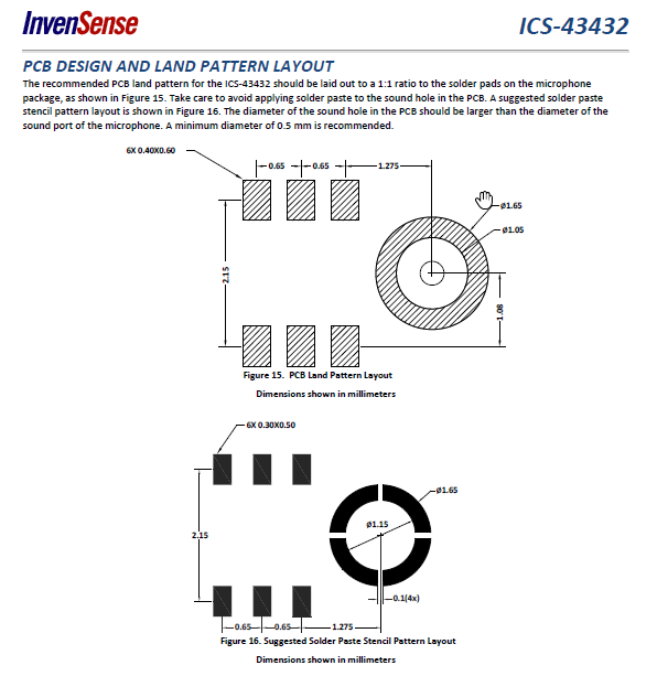
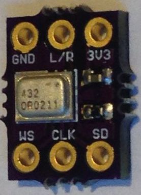
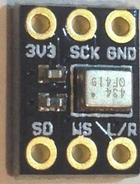
The ICS43432 seems to be quite expensive with 14.90 EUR excl. tax but is really tiny and fits so between two combs easily. But you can get the InvenSense ICS43432 mic really cheap without PCB! Unfortunately it’s a bit tricky to solder it on an PCB and you need a stencil, solder paste and an oven, see p. 16;
I told some people about my effort to get the I2S stuff working some days ago. I had initially problems to get the things working. My combinations of IDE and libs made some problems that ends in an compilation error. The solution was to update to the last Arduino IDE version 1.8.2 and the latest libs.
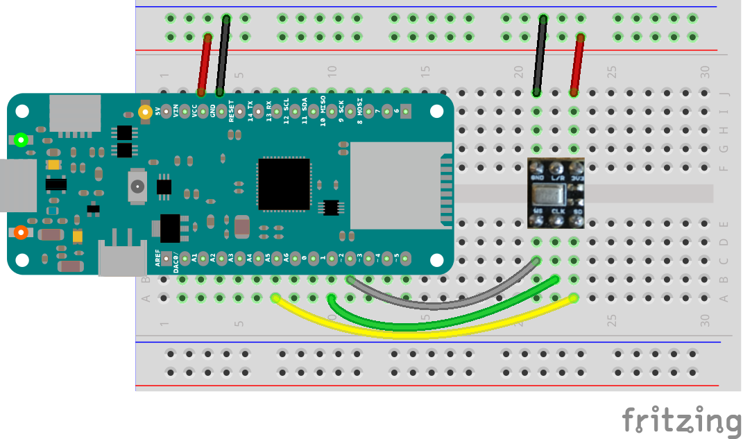
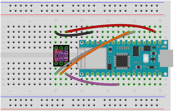
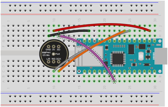
There is an error in the wiring diagram. The lower wires (yellow, green gray) are displaced by 1 pin to the left by mistake! Correct is the wiring / pins as described above.
The great thing about this is you can perform a FFT with different custom parameter. So in the end you can have a profile of the current sound event.
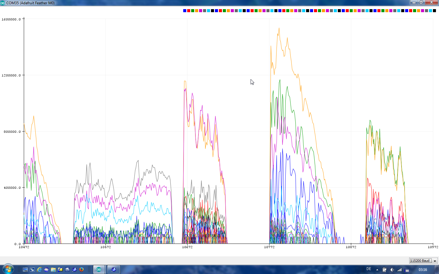
To use not only the textual output but the serial plotter you have to modify the the code like mentioned in the first posting and describe on the Adafruit page:
/*
 This example reads audio data from an Invensense's ICS43432 I2S microphone
 breakout board, and prints out the spectrum to the Serial console. The
 Serial Plotter built into the Arduino IDE can be used to plot the audio
 amplitude data (Tools -> Serial Plotter)

 Circuit:
 * Arduino/Genuino Zero, MKRZero or MKR1000 board
 * ICS43432:
   * GND connected GND
   * 3.3V connected 3.3V (Zero) or VCC (MKR1000, MKRZero)
   * WS connected to pin 0 (Zero) or pin 3 (MKR1000, MKRZero)
   * CLK connected to pin 1 (Zero) or pin 2 (MKR1000, MKRZero)
   * SD connected to pin 9 (Zero) or pin A6 (MKR1000, MKRZero)

 created 21 November 2016
 by Sandeep Mistry
 */

#include <ArduinoSound.h>

// sample rate for the input
const int sampleRate = 8000;

// size of the FFT to compute
const int fftSize = 128;

// size of the spectrum output, half of FFT size
const int spectrumSize = fftSize / 2;

// array to store spectrum output
int spectrum[spectrumSize];

// create an FFT analyzer to be used with the I2S input
FFTAnalyzer fftAnalyzer(fftSize);

void setup() {
// Open serial communications and wait for port to open:
  // A baud rate of 115200 is used instead of 9600 for a faster data rate
  // on non-native USB ports
  Serial.begin(115200);
  while (!Serial) {
    ; // wait for serial port to connect. Needed for native USB port only
  }

  // setup the I2S audio input for the sample rate with 32-bits per sample
  if (!AudioInI2S.begin(sampleRate, 32)) {
    Serial.println("Failed to initialize I2S input!");
    while (1); // do nothing
  }

  // configure the I2S input as the input for the FFT analyzer
  if (!fftAnalyzer.input(AudioInI2S)) {
    Serial.println("Failed to set FFT analyzer input!");
    while (1); // do nothing
  }
}

void loop() {
  // check if a new analysis is available
  if (fftAnalyzer.available()) {
    // read the new spectrum
    fftAnalyzer.read(spectrum, spectrumSize);

    // print out the spectrum
    for (int i = 0; i < spectrumSize; i++) {
      //Serial.print((i * sampleRate) / fftSize); // the starting frequency
      Serial.print(spectrum[i]); // the spectrum value
      Serial.print("\t");
    }
    Serial.println(); //
  }
}
sampleRate = 8000
This is the sample rate in Hz - sample rate must be double of the frequency you want to measure at maximu, so with the above parameter “8000” you can measure sound up to 4 kHz
fftSize = 128
this is not the number of bins, but the half of it, see
spectrumSize = fftSize / 2;
size of the spectrum output, half of FFT size
the last paramter is defined in the i2S.begin bitsPerSample is the second parameter,
bits per sample: 8, 16, 32 are noted in the documentation.
Note: Seems that not all combinations of this parameters are possible. Playing around with different values lead in my tests sometimes to non or negative output (values),
The SpectrumSerialPlotter.ino example uses the FFTAnalyzer.h which includes #include <arm_math.h> for the FFT part. So we can not count on this for an ESP32 implementation.
No way for audio samples! ;-) Not only the data volume is too much also the allowed duty cycle will be too high in case we would make it not real time but asynchronous.
Frequency diagrams is also too much but you can send aggregated (is the mean enough?) data like one single valu for lets say 64 bins you have as output from a FFT.
Ok. So a really good data connection would be needed to collect audio data.
About what volume of data do we talk? How big is a 1 minute recording with this codec-less I2S microphone? How big would the FFT analyses be for 1 minute recording?
Lets say we can use GPRS (besides the costs for traffic) what about the power the sending of such large files would drain from the battery. Do you think this setup would still be possible with a solar powered system?
How often would you record audio data per day? I mean not only to detect the current state of the hive, but to submit the audio data to OSBH machine learning server.
hmm… no need to use bandwidth and remote servers for such things rather than using local software. You could use the generate/tone function in Audacity:
… is a broad field. Yes, I think raw or even mp3 encoded “real” audio data is a subject for WiFi or Ethernet first. But it belongs mainly on the kind of (audio) data we need. Do we need 2 minutes or is 5 seconds also sufficient? Do we need samples every hour or is once a day ok? Do we need “real” audio data or is a aggregated data format sufficient?
It seems that for the OSBH algorithm some seconds are enough to get a state. More than some seconds do not lead to other states but only to a more valid decision base.
We had a look in the code bud could not check it in detail but it seems that some kind of aggregation is done before the learning algorithm to output the hive state. so it seems that we can submit only aggregated data or even better all analysis is done on the node and we submit the result of the “calculation” only.
Atm we have no insides about the learning algorithm. In case we will train the magic machine also we have to transfer more detailed sound data for OSBH.
My starting point - beside OSBH - would be to make FFTs on the node not once one millisecond, but some seconds or even minutes. Now I would calculate the mean for let’s say 64 frequency bins and send this via radio or GSM to a server. We could make this with known (beekeeper diary/Stockkarte) state. So we can compare the data and see if we can find a discrimination function for our states based on the power level of different frequency bins.
My thought is to get alerts of different hive states via LoRaWAN. But for the actual audio swap a SD card over when I visit the bees and upload it to OpenSourceBeehives/ the internet. Old school sneakernet. That way everyone gets what they need I think.
@permagriculture Yes, that could be a possible solution for me too. My Autonomo has a sdcard slot too.
OSBH want to provide @clemens a developer box of their data collection system (see here). For my part I will wait until we know little bit more about how they collect and process recordings for further analysis.
With a bit distance I see that the title of this thread “Sound Recording” is a bit misleading. ;-) Up to now we have not recorded any sound but only recorded FFT analysing data.
I try to find out if it is also possible to record audio data, e.g. as wave or mp3 or ogg with a Cortex M0 and the Arduino I2S and / or Arduino Sound lib, see this thread on the Arduino forum: http://forum.arduino.cc/index.php?topic=538523.0
In case you have no official documentation or information about the Arduino pins used for I2s, have a look at the corresponding variant.h file of the board.
I’d like to use the Arduino Nano 33 IoT, a cheap Cortex M0 board with WiFi (via u-blox NINA-W102), so I have to inspect: