I2S-Mikrophon mit FiPy und Arduino-IDE zum Laufen bringen

Versuche gerade diese Beispiel

Mit einem einem FiPY und einem INMP441 I2S-Mikrofon zum Laufen zu bringen. Das Mikro habe ich vorher mit einem Arduino Nano 33 IoT getestet, was funktionierte, der code oben läuft leider nicht.

Programmierung

Der FiPy ist am expansion board angeschlossen, das per USB-Kabel am Rechner hängt. Vor dem Aufspielen der Arduino-Software müssen wir das board in den bootloader mode bekommen, das geht so:
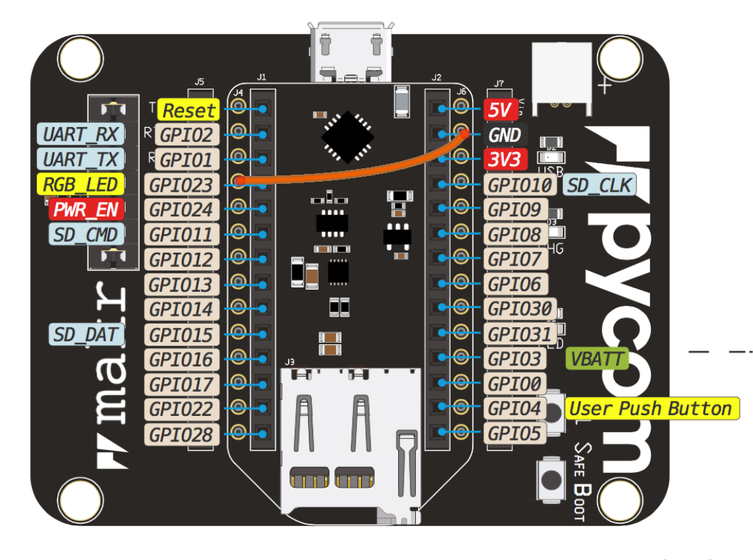
  1. die pins G23 und GND mit einem jumper wire verbinden, so wie hier:
  2. dann reset am FiPy drücken

(Siehe dazu auch Program your LoPy from the Arduino IDE, using LMIC - Stories - Labs > Program the LoPy)

Pin-Nummerierung bei Verwendung der Arduino-IDE

Bei Verwendung der Arduino-IDE dürfen wir nicht die Pin-Nummern P1, P2, usw. im pinout diagram verwenden, sondern die Nummerierung bei GPIO

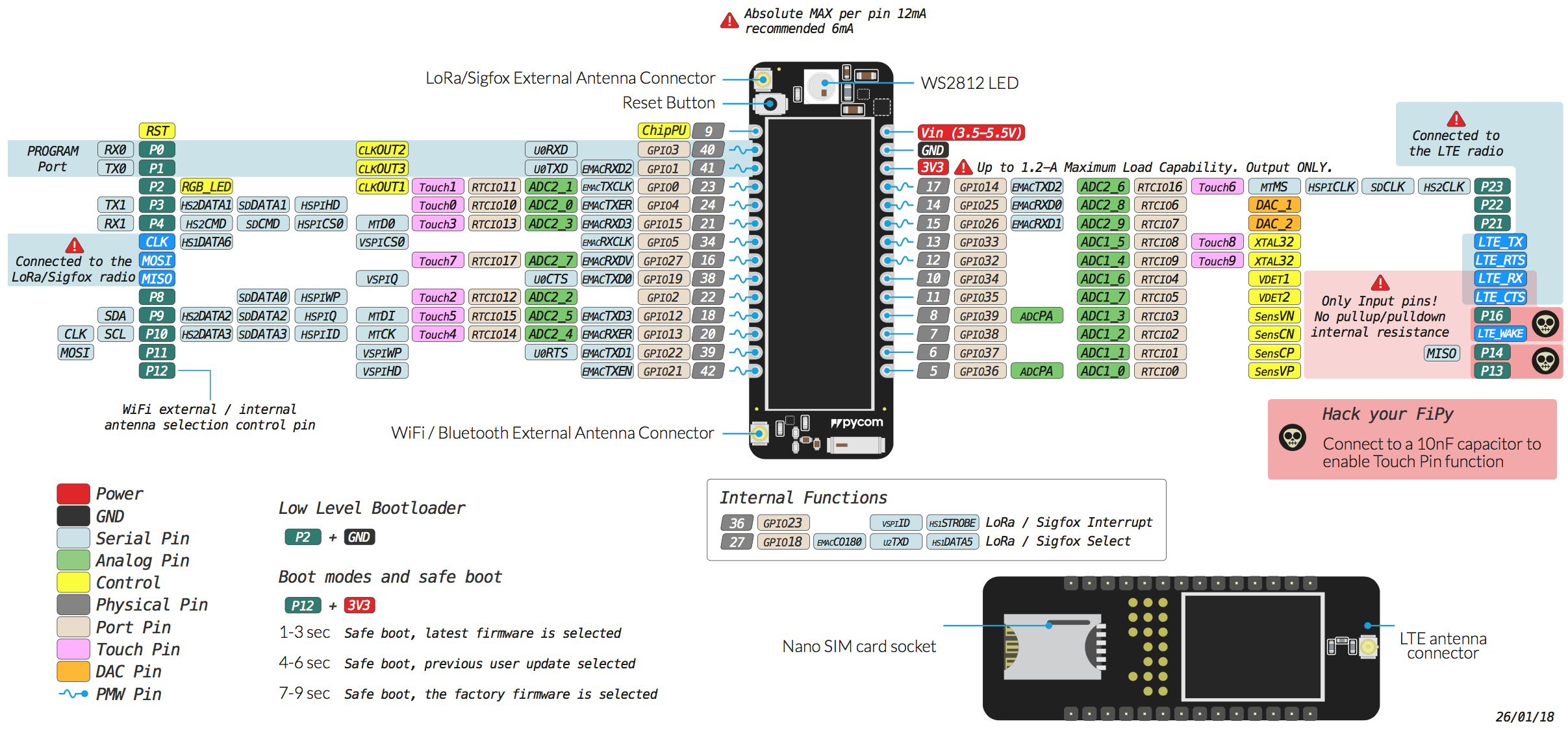
(Siehe auch Using PyCom boards with Arduino IDE | Pycom user forum )

Code-Änderungen

Mit diesen Anpassungen …

  // The pin config as per the setup
  const i2s_pin_config_t pin_config = {
      .bck_io_num = 22,   // BCKL
      .ws_io_num = 25,    // LRCL
      .data_out_num = -1, // not used (only for speakers)
      .data_in_num = 26   // DOUT
  };

… sollte das wiring wie hier passen:

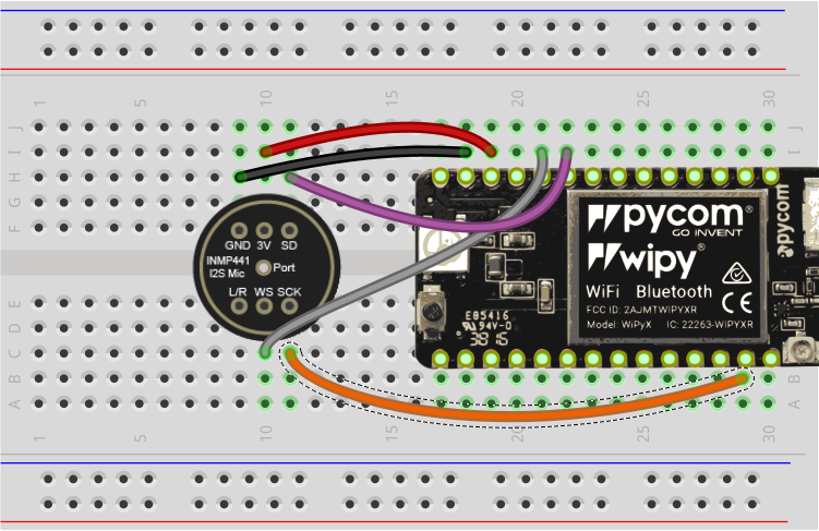
[edit] In einer älteren Version des Postings waren andere pins angegeben, die zu Konflikten mit der SD-Karte geführt haben. Nun geht es mit der Pinbelegung oben! Yeah!
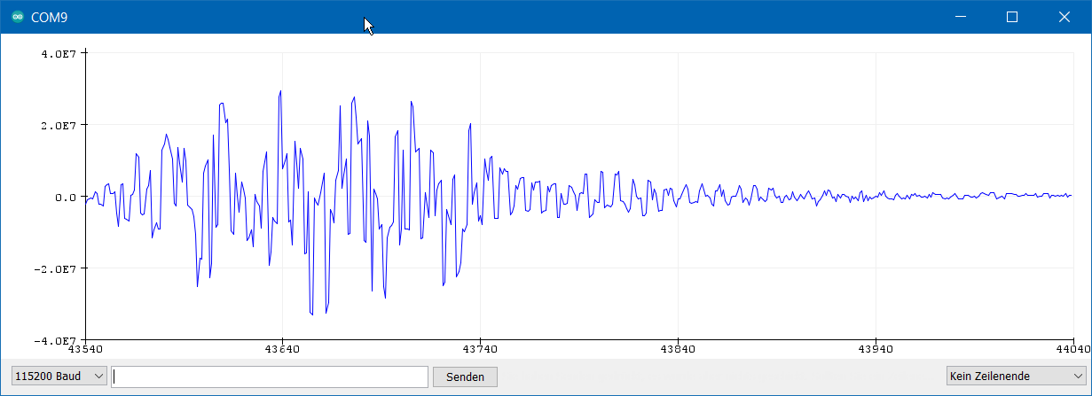
Problem

Nun wird immer 0 über den seriellen Monitor ausgegeben egal wie tief / laut / leise das Geräusch am Mikrofon ist. Was geholfen hat ist den rechten channel auf den linken umzuschalten, statt:

  .channel_format = I2S_CHANNEL_FMT_ONLY_RIGHT, // although the SEL config should be left, it seems to transmit on right

… das hier:

  .channel_format = I2S_CHANNEL_FMT_ONLY_LEFT, // although the SEL config should be left, it seems to transmit on right

Output

Gerade getestet! Das funktioniert auch auf dem FiPy mit Arduion-IDE. Für die eigentliche FFT wird die Arduino-Bibliothek arduinoFFT von Enrique Condes / kosme verwendet, die über den Arduino-Bibliotheksmanager zugänglich ist.

Den web-Kram rausgeschmissen, working code
/*------------------------------------------------------------------------------
  Code by squix78.

  Do you like this sample? Support my work by teleporting a coffee to me:
  https://www.paypal.com/paypalme2/squix78/5

  In this blog post I described how the code works: 
  https://blog.squix.org/2019/08/esp32-esp-eye-browser-based-spectrum-analyzer.html

  
*/

#include <Ticker.h>
#include <arduinoFFT.h>
#include <driver/i2s.h>

const i2s_port_t I2S_PORT = I2S_NUM_0;
const int BLOCK_SIZE = 512;

const double signalFrequency = 1000;
const double samplingFrequency = 10000;
const uint8_t amplitude = 150;

double vReal[BLOCK_SIZE];
double vImag[BLOCK_SIZE];
int32_t samples[BLOCK_SIZE];

String labels[] = {"125", "250", "500", "1K", "2K", "4K", "8K", "16K"};

arduinoFFT FFT = arduinoFFT(); /* Create FFT object */

int bands[8] = {0, 0, 0, 0, 0, 0, 0, 0};

void setupMic() {
  Serial.println("Configuring I2S...");
  esp_err_t err;

  // The I2S config as per the example
  const i2s_config_t i2s_config = {
      .mode = i2s_mode_t(I2S_MODE_MASTER | I2S_MODE_RX), // Receive, not transfer
      .sample_rate = samplingFrequency,                        
      .bits_per_sample = I2S_BITS_PER_SAMPLE_32BIT, // could only get it to work with 32bits
//      .channel_format = I2S_CHANNEL_FMT_ONLY_RIGHT, // although the SEL config should be left, it seems to transmit on right
      .channel_format = I2S_CHANNEL_FMT_ONLY_LEFT, // although the SEL config should be left, it seems to transmit on right
      .communication_format = i2s_comm_format_t(I2S_COMM_FORMAT_I2S | I2S_COMM_FORMAT_I2S_MSB),
      .intr_alloc_flags = ESP_INTR_FLAG_LEVEL1,     // Interrupt level 1
      .dma_buf_count = 4,                           // number of buffers
      .dma_buf_len = BLOCK_SIZE                     // samples per buffer
  };

  // The pin config as per the setup
    i2s_pin_config_t pin_config = {
        .bck_io_num = 12,   // IIS_SCLK
        .ws_io_num = 15,    // IIS_LCLK
        .data_out_num = -1, // IIS_DSIN
        .data_in_num = 35   // IIS_DOUT
    };

  // Configuring the I2S driver and pins.
  // This function must be called before any I2S driver read/write operations.
  err = i2s_driver_install(I2S_PORT, &i2s_config, 0, NULL);
  if (err != ESP_OK) {
    Serial.printf("Failed installing driver: %d\n", err);
    while (true);
  }
  err = i2s_set_pin(I2S_PORT, &pin_config);
  if (err != ESP_OK) {
    Serial.printf("Failed setting pin: %d\n", err);
    while (true);
  }
  Serial.println("I2S driver installed.");
}

void setup() {
  Serial.begin(115200);
  delay(1000);
  Serial.println("Setting up mic");
  setupMic();
  Serial.println("Mic setup completed");

  delay(1000);
}

void loop() {
  // Read multiple samples at once and calculate the sound pressure

  int num_bytes_read = i2s_read_bytes(I2S_PORT, 
                                      (char *)samples, 
                                      BLOCK_SIZE,     // the doc says bytes, but its elements.
                                      portMAX_DELAY); // no timeout

  for (uint16_t i = 0; i < BLOCK_SIZE; i++) {
    vReal[i] = samples[i] << 8;
    vImag[i] = 0.0; //Imaginary part must be zeroed in case of looping to avoid wrong calculations and overflows
  }

  FFT.Windowing(vReal, BLOCK_SIZE, FFT_WIN_TYP_HAMMING, FFT_FORWARD);
  FFT.Compute(vReal, vImag, BLOCK_SIZE, FFT_FORWARD);
  FFT.ComplexToMagnitude(vReal, vImag, BLOCK_SIZE);
  for (int i = 0; i < 8; i++) {
    bands[i] = 0;
  }
  
  for (int i = 2; i < (BLOCK_SIZE/2); i++){ // Don't use sample 0 and only first SAMPLES/2 are usable. Each array eleement represents a frequency and its value the amplitude.
    if (vReal[i] > 2000) { // Add a crude noise filter, 10 x amplitude or more
      if (i<=2 )             bands[0] = max(bands[0], (int)(vReal[i]/amplitude)); // 125Hz
      if (i >3   && i<=5 )   bands[1] = max(bands[1], (int)(vReal[i]/amplitude)); // 250Hz
      if (i >5   && i<=7 )   bands[2] = max(bands[2], (int)(vReal[i]/amplitude)); // 500Hz
      if (i >7   && i<=15 )  bands[3] = max(bands[3], (int)(vReal[i]/amplitude)); // 1000Hz
      if (i >15  && i<=30 )  bands[4] = max(bands[4], (int)(vReal[i]/amplitude)); // 2000Hz
      if (i >30  && i<=53 )  bands[5] = max(bands[5], (int)(vReal[i]/amplitude)); // 4000Hz
      if (i >53  && i<=200 ) bands[6] = max(bands[6], (int)(vReal[i]/amplitude)); // 8000Hz
      if (i >200           ) bands[7] = max(bands[7], (int)(vReal[i]/amplitude)); // 16000Hz
    }

    //for (byte band = 0; band <= 6; band++) display.drawHorizontalLine(18*band,64-peak[band],14);
  }

  for (int i = 0; i < 8; i++) {
    Serial.print(String(bands[i]));
    Serial.print(",");
  }
  Serial.println();
}
2 Likes

Hier noch etwas interessantes gefunden: https://forum.arduino.cc/index.php?topic=637667.0 Da hat jemand versucht I2S-Daten mit #include <arduinoFFT.h> zu bearbeiten.

edit: sollte prinzipiell gehen, s. MEMS + ESP32 + FFT · Issue #34 · kosme/arduinoFFT · GitHub

1 Like