Hello from Romania

Hello,

Thank you for accepting me to the forum.

My name is Octavian Ureche, I’m from Brasov, central Romania.
I’m a beekeeper myself, also my father is, but because of his age I’m attending the hives now.

I was contempling of buiding a bee hive monitor for several years. I had limited electronics knowledge and no programming skills. Of course I started with an Arduino R3 board by adding sensors. I understood that the Hive sensor needed to be a low power device, arduino is not such thing.

I spent time doing a lot of learning and a lot of research on the internet - this is how I found “The Hiveeyes Project”.

Currently I built one “sensor node” (Hivemon V1), is deployed and it is sending data from last autumn.
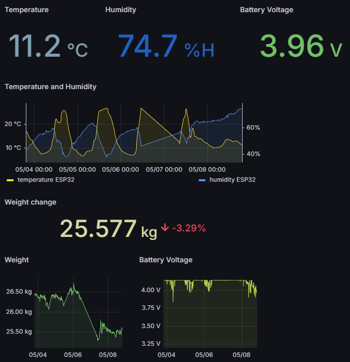
The device is hybrid powered solar/battery, measured data visualization is done on pc or mobile.

Measured data: hive weight, outside temperature & humidity, battery voltage
Data read at each 15 minutes and then ESP32 sleep

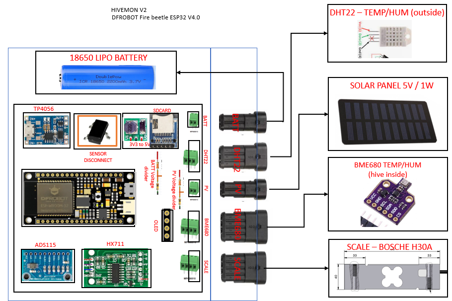
Hardware details (Hivemon V1):

  1. ESP32 Firebeetle - low power
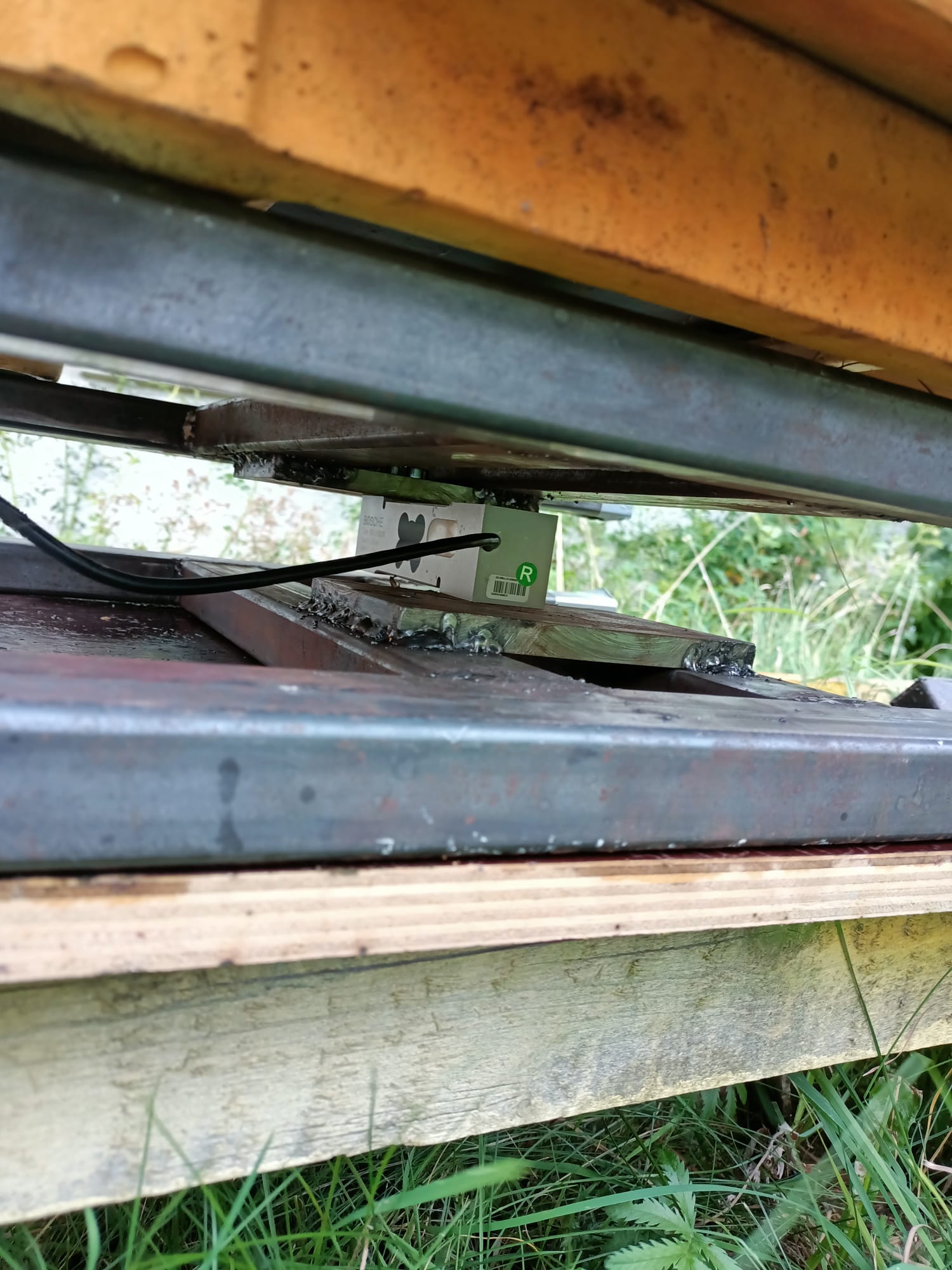
  2. HX711 scale driver + BOSCHE HW30 load cell
  3. DHT22 sensor
  4. Solar panel 1W / 5Volts + 18650 2200mAh LiPo + TP4056 solar charger module

Data communication / visualization: Sensor read > ESP32 WIFI > InfluxDB > Grafana

For the actual loadcell support (scale) I use the “double H” model I saw on the “Hiveeyes”. I hope it is ok to use it.

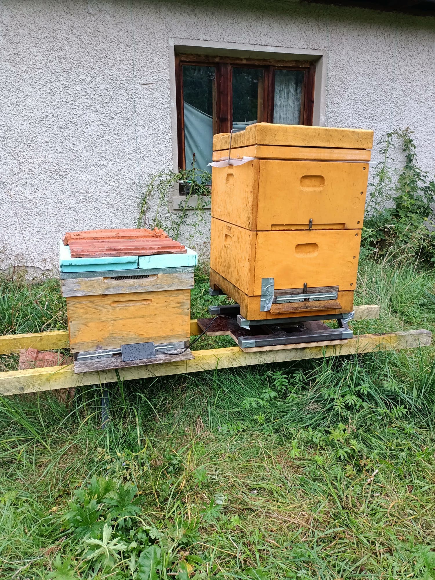
Hivemon V1 (details in the picture below) is a prototype I built just to see if it actually works, and to verify if it can be deployed a a long time (at least several months) without changing the battery.
I had also some issues, sensor sending data intermitently, the wifi signal from my router was not strong enough, so I had to install a range extender. No problems since.

Basically it can send data for up to 6 days without charging the battery.

I’m planning an upgraded version of the sensor. It will include a sensors on/off switch (with a Mosfet) and a BME680 sensor to be installed inside the hive.

Below are a few pictures of my bees and the HivemonV1 sensor installed, and the grafana dashboard.
I’ll be happy to share more pictures, currently there is a limitation for new users.

The work on this sensor was a learning journey for me and to see the first measurements on Grafana was a dream come true.

Actually reading through the forum and looking at the nice Grafana dashboards, make up my mind to really finish this project (it is nor really finishes but it works :grinning: ).

Thank you for sharing and spreading the knowledge.

Sorry for the long post.

If there are any questions regarding the build or bees & beekeeping, I’ll be glad to answer.

Bst wishes,
Octavian

3 Likes

Dear Octavian,

thanks for sharing a few details about your setup, and welcome to the community. Please let us know if you…

a) Would like to contribute your firmware code to GitHub - hiveeyes/arduino: Arduino-compatible MCU firmware code for sensor-, telemetry-, and gateway-appliances..

b) If you would like to re-use our telemetry data acquisition middleware and backend software, eventually in order to collaborate on it. Let us know if you missed that up until now, and if you would like to learn more about it.

Cheers,
Andreas.

Thanks for sharing your setup, @Octavian!

I thought about similar things, but the used sensors – on my side HX711, DS18B20, BME680 – have proper low power settings you can activate by software and I see no need to intervent at this point. Wifi needs so much energy in comparison, so better optimise on other points instead of sensor energy consumption.

Did you use the ESP32 low power option? This would my favourite to reduce power.

Hello clemens,

Sure, you are right, for the mentioned devices there are low power modes that can be activated by software. But besides those there are some that remain always powered on (on my V2 board is the ADS1115 and DHT22 and the micro SD module).

I prefer to solve this problem with in a single solution, wich is the Mosfet switch. Of course, I’ll test the setup if really makes the difference in the field, and those drops in the voltage during the night will decrease, compared to the V1 set-up.

Below is the planned V2 board layout (it fits on 10X10 cm PCB).

Details:

  • I’m thinking to use automotive type connectors (they have water protection) for rapid servicing if it is the case.
  • DHT22 is meant to sit inside the Hivemon case but there is little to no difference between outside and inside Hivemon case temp/hum
  • OLED connection (I2C) is just for testing during build (no usb connection)
  • microSD card is added for back-up when there is no wifi connection for some reason, but I’m still thinking if I’ll keep it or not because I have to include the boost converter 3V3 to 5V and I think the power draw is quite big during read/writes - I tried to use ESP32 internal memory but for some reason it did not worked, I have to revisit the topic

Best regards,
Octavian

Hello Andreas,

Regarding your questions:

a) Sure, I would like to submit the Hivemon firmware to Hiveeyes GitHub. I have to read the details on how to do it. :grinning:

b) I’m not planning to use telemetry data aquisition and/or software described on the forum.
I try to expand my limited knowledge by reading topics and testing specific items I intend to include in my Hivemon solution only. At least for the moment.

Thank you,
Octavian

1 Like

Hello clemens,

I forgot to add that I’m using indeed ESP32 low power.
Data read at each 15mins and back to sleep.

There is a catch here, not every ESP32 board is suited for low power usage. Actually most of them are not. I’m using ESP32 Firebeetle from DFRobot, and it is working fine.

It draws 10 to 80mA during wake-up: measuring and data transmission.
Wake up time is between 6 to 12 seconds but can be different due to wifi connection initialisation.

Best regards,
Octavian

1 Like

Hello all,

I’m sharing some pictures of my set-up:
It looks like a mess sorry for that.


My bees last year before adding the sensor scale:

Best regards,
Octavian

3 Likes

Nice setup Octavian! For your future plans I would not count on the DHT22, we have used them a lot in the past and did it not longer than one year because it was then broken, at least humidity measurement did no more work. And in addition it is not very accurate! So in case you have a BME already, I would also use a BME 260 outside for temperature and humidity.

About the TP4056, this is not a dedicated solar charger IC so I would use another module, perhaps the CN3065, I used them since a long time and perhaps there are better IC available in the meantime, see also:

On my first hive monitoring setups I have used the Seeeduino Stalker also with SD card on board. For a time I logged also on SD but never used the data. My experience: Either you have the data transmitted and in a nice system online or you will never use the data because it is complicated and time consuming to copy them from SD to the database. It may be another thing if you would like to monitor data in a scientific setting with now or never time constrains. It took a time to say goodbye to the good old SD but I don’t miss it. Also because SD card interfaces need much energy and 5 V a lot of pins and so it makes the setup a lot more complicated.

Btw. what is the ADS1115 for?

I have started – a longer time ago – a PCB design for the Firebeetle 2 (it has castellated holes and so you can is solder directly on the PCB) with a very similar setting as you and in addition a GSM / GPRS module, I2S micro and a LoRa / TTN module. Just as “preview”, it’s not fully working and I run out of pins for all periphery so still lot work to do, just to confirm, that I think the Firebeetle is a good base! :-)

Hello clemens,

Thank you for the advices.

I’ll replace DHT22 I already have the BME280.

Regarding TP4056, as I said, I’m no electronics expert so I did my research. I use the T4056 solar charger in the configuration described by Mr. Andreas Spiess in this video (see at min: 9:50):

Also in another video Mr. Spiess did a evaluation of a series of solar chargers suitable for small outdoor projects:

Regarding the the microSD card module, I’ll probably keep it, even if it is a bit of a hassle with the installation (5V power supply and and amount of power drawn while in operation)

ADS1115 is a small analog to digital converter, and I’ll use it to measure the battery voltage and the solar panel voltage while charging. There are limited suitable ADC GPIO’s on the Firebeetle ESP32 and I decided to use the separate ADC board. This board has 4 input pins, I’ll use two, and give up on the ESP32 ADC. I hope it will work. It will share the I2C bus with the BME sensor.

Thank you for showing interest in my build ,it is basically a LEGO model composed from a lots of solutions or advices, I saw or read on the internet. I’m happy version V1 works =).

If there are questions I’m glad to answer.

Best regards,
Octavian

good evening octavian,
i am very glad you found your way to hiveeyes and presented in such a detail. i am really enjoying to read it.
best,
markus

1 Like