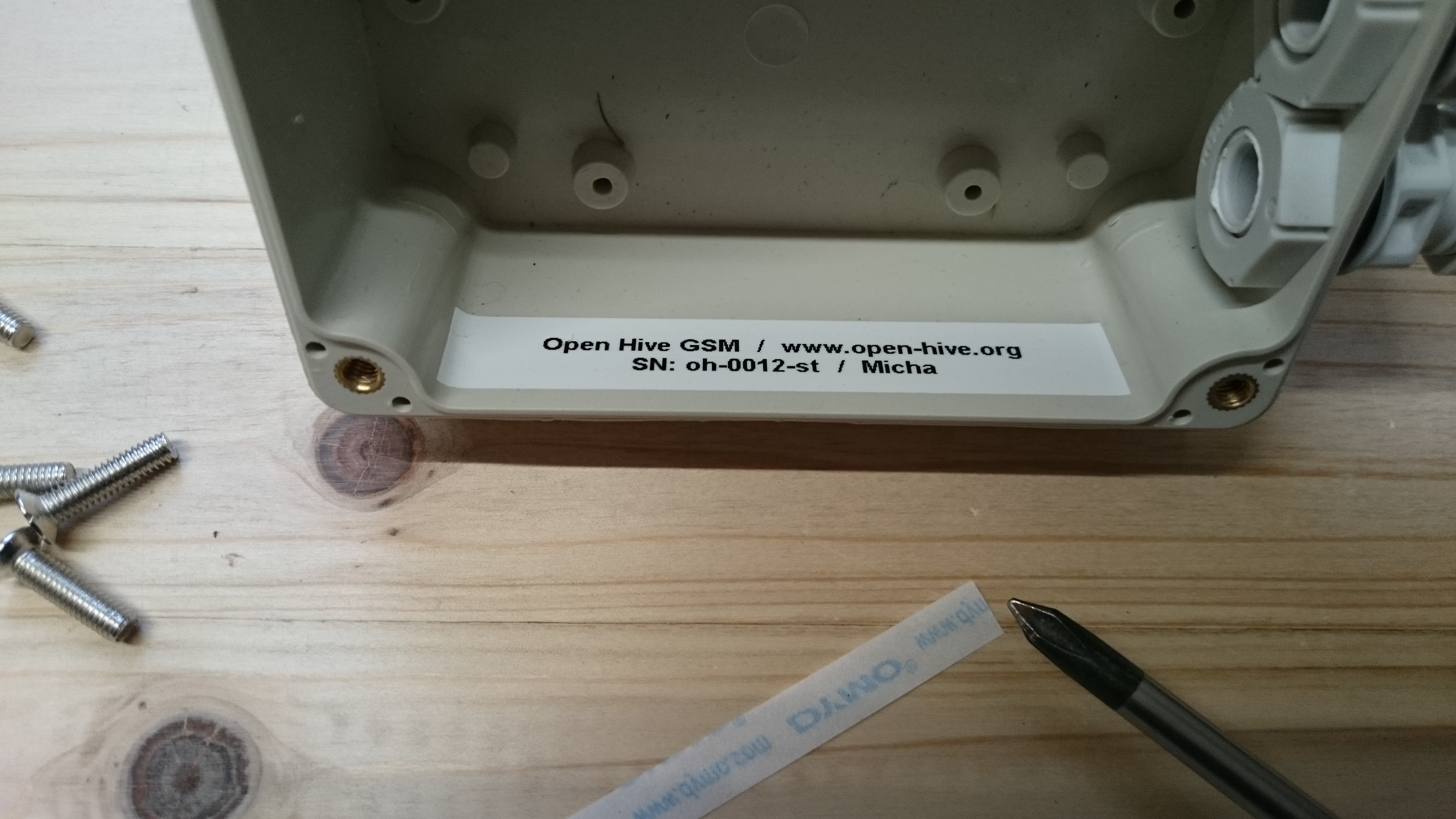
First thing: We have to do some documentation: The first Open Hive electronic boxes does not have a serial number only, but also a personalized user name!
Electronic Connections
The real first assembly step is to reduce the diameter of the load cell’s shielding cable so that it fits in the screw terminal. Take a box cutter or wire cutter and divide the shielding cable and cut the second part down.
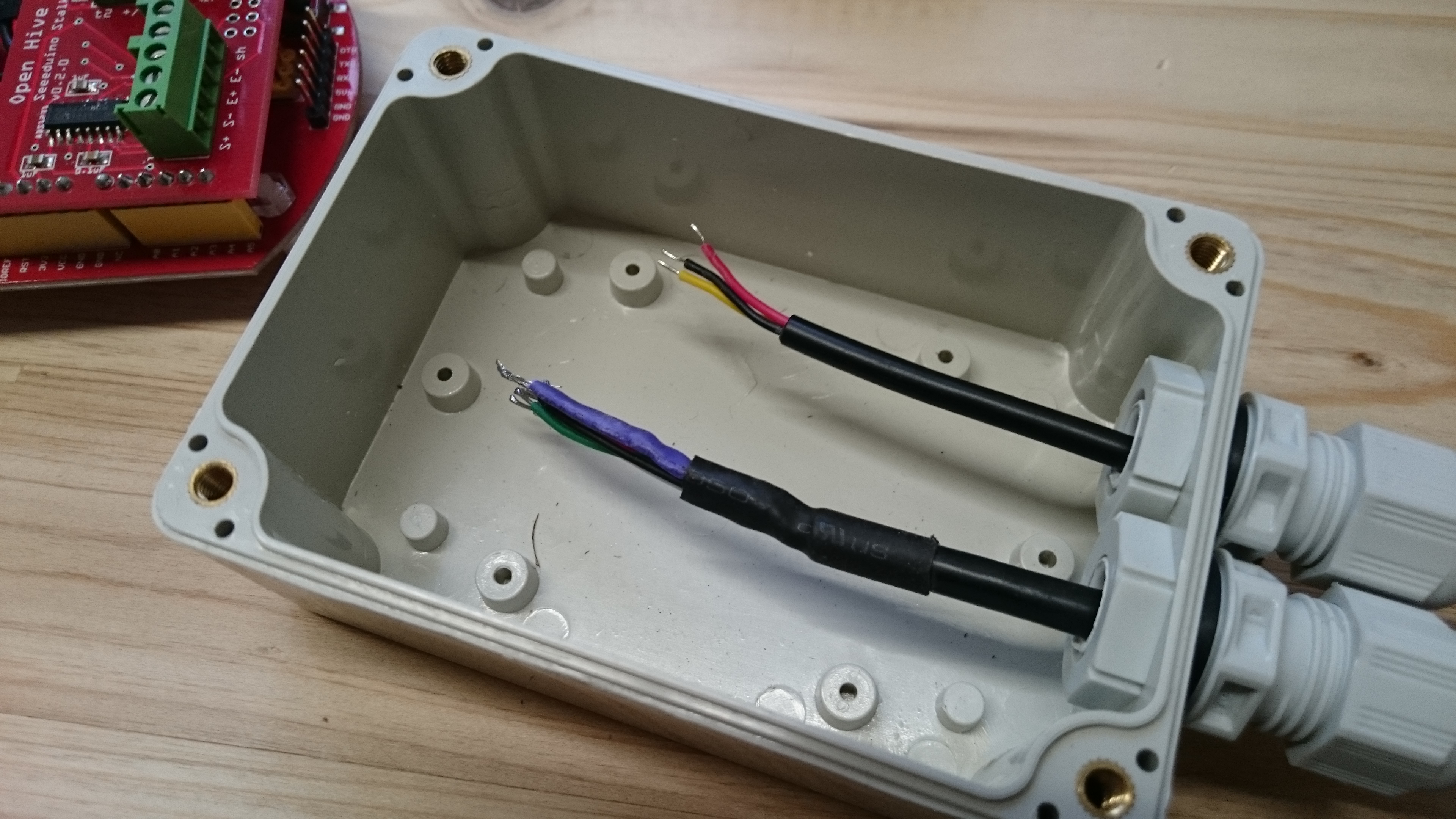
Put the cable through the cable glances.
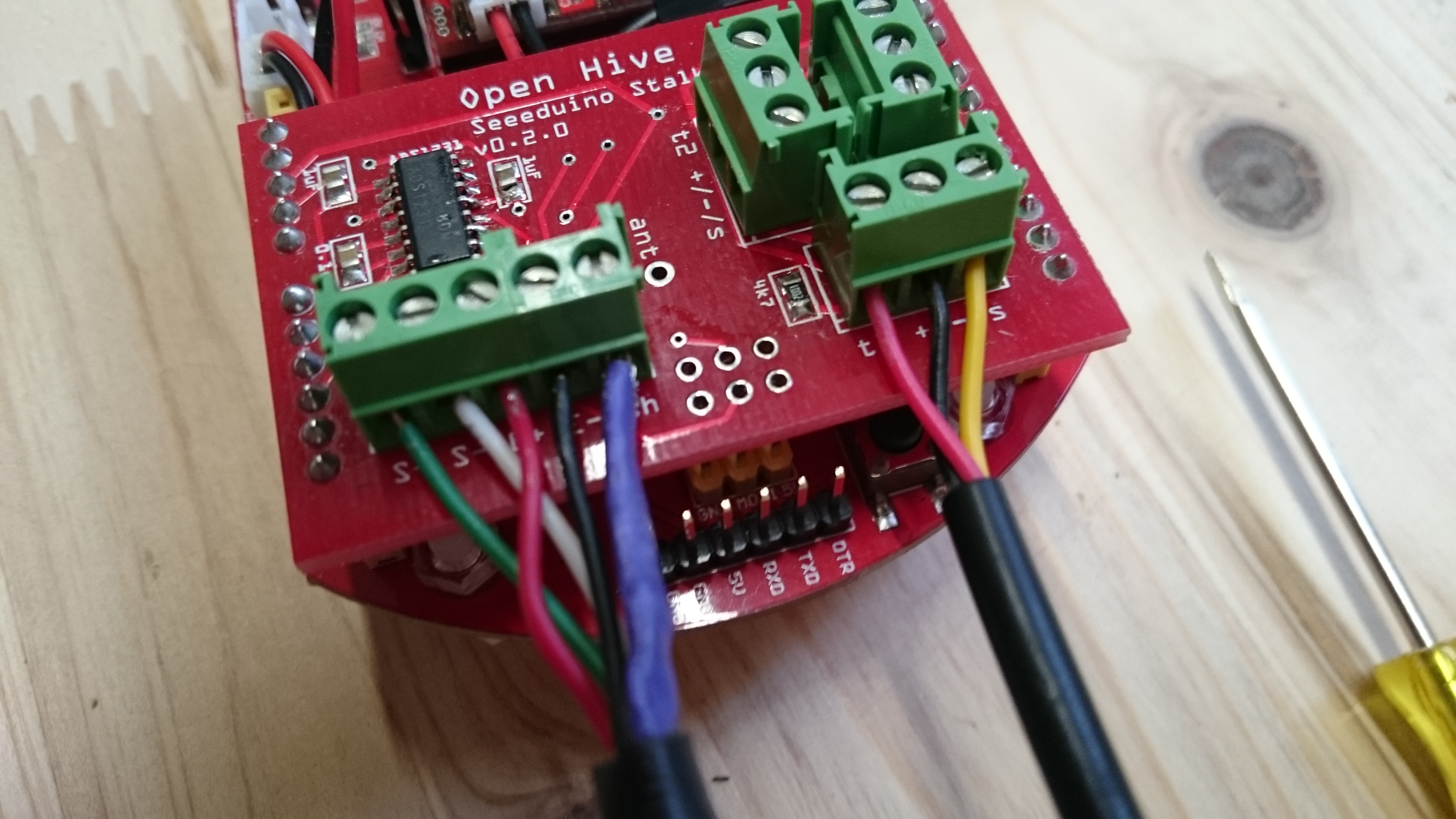
Screw tightly the cables of the load cell and the sensors.
for the load cell
S+     S-     E+     E-`    sh
green  white  red    black  violet
for the sensors
+/Vcc   -/GND   Sense
red     black   yellow
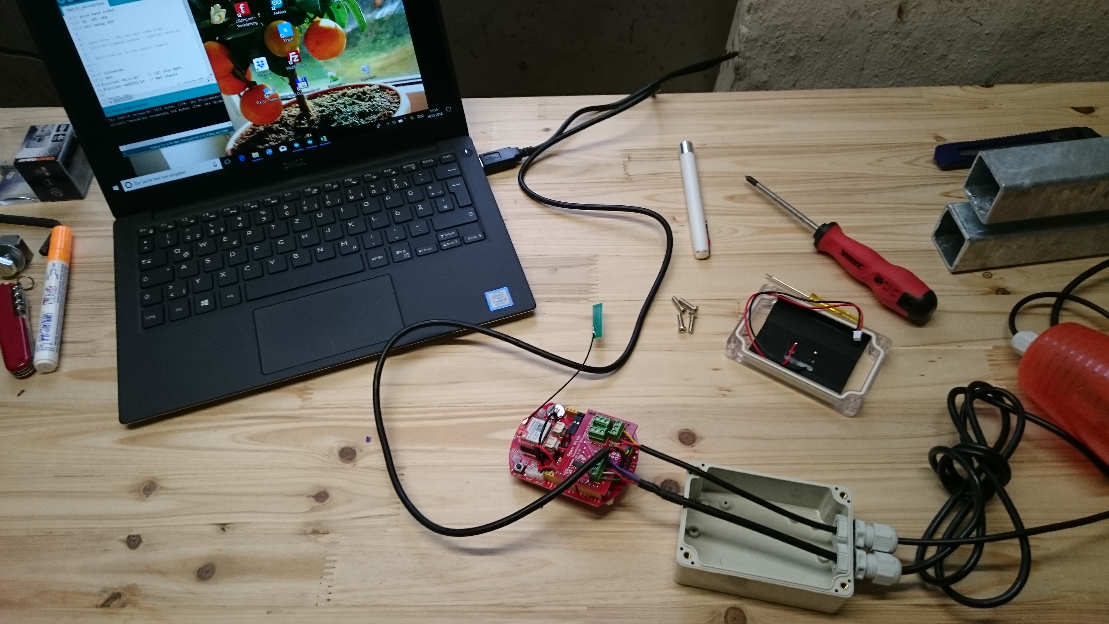
So we have all electrical connections we need and can start programming. Connect the board with an FTDI cable to the computer.
Software Uploading …
Used Libraries
-
Low Power
download/git: https://github.com/rocketscream/Low-Power/archive/master.zip
documentation: http://www.rocketscream.com/blog/2011/07/04/lightweight-low-power-arduino-library/
Version/Date: v1.60, 2016-04-01 -
load cell / HX711
download/git: https://github.com/bogde/HX711/archive/master.zip
documentation: https://github.com/bogde/HX711
Version/Date: v0.1, 2017-01-11 -
load cell / ADS1231
download/git: http://forum.arduino.cc/index.php?action=dlattach;topic=131086.0;attach=67564
documentation: http://forum.arduino.cc/index.php?topic=131086.msg1570340#msg1570340
Version/Date: 2014-01-31 -
running median / statistics
download/git: https://github.com/RobTillaart/Arduino/archive/master.zip
documentation: https://github.com/RobTillaart/Arduino/tree/master/libraries/RunningMedian
Version/Date: v0.1.14, 2018-01-09 -
RTC
download/git: https://github.com/jcastaneyra/ds3231_library/archive/master.zip
documentation: https://github.com/jcastaneyra/ds3231_library/
Version/Date: 2014-05-01 -
DS18B20 / OneWire
!! deactivate for DS18B20 in in the latest version !!
download/git: https://github.com/PaulStoffregen/OneWire/archive/master.zip
documentation: https://github.com/PaulStoffregen/OneWire
Version/Date: v2.3.2, 2017-09-05 -
DS18B20 itself
download/git: https://github.com/milesburton/Arduino-Temperature-Control-Library/archive/master.zip
documentation: https://github.com/milesburton/Arduino-Temperature-Control-Library/
Version/Date: v3.7.8, 2018-01-09 -
DHT
download/git: https://github.com/RobTillaart/Arduino/archive/master.zip
documentation: https://github.com/RobTillaart/Arduino/tree/master/libraries/DHTstable
Version/Date: v0.2.2, 2018-01-09 -
GPRSbee
download/git: https://github.com/SodaqMoja/GPRSbee/archive/master.zip
documentation: https://github.com/SodaqMoja/GPRSbee
Version/Date: v1.9.2, 2016-07-05
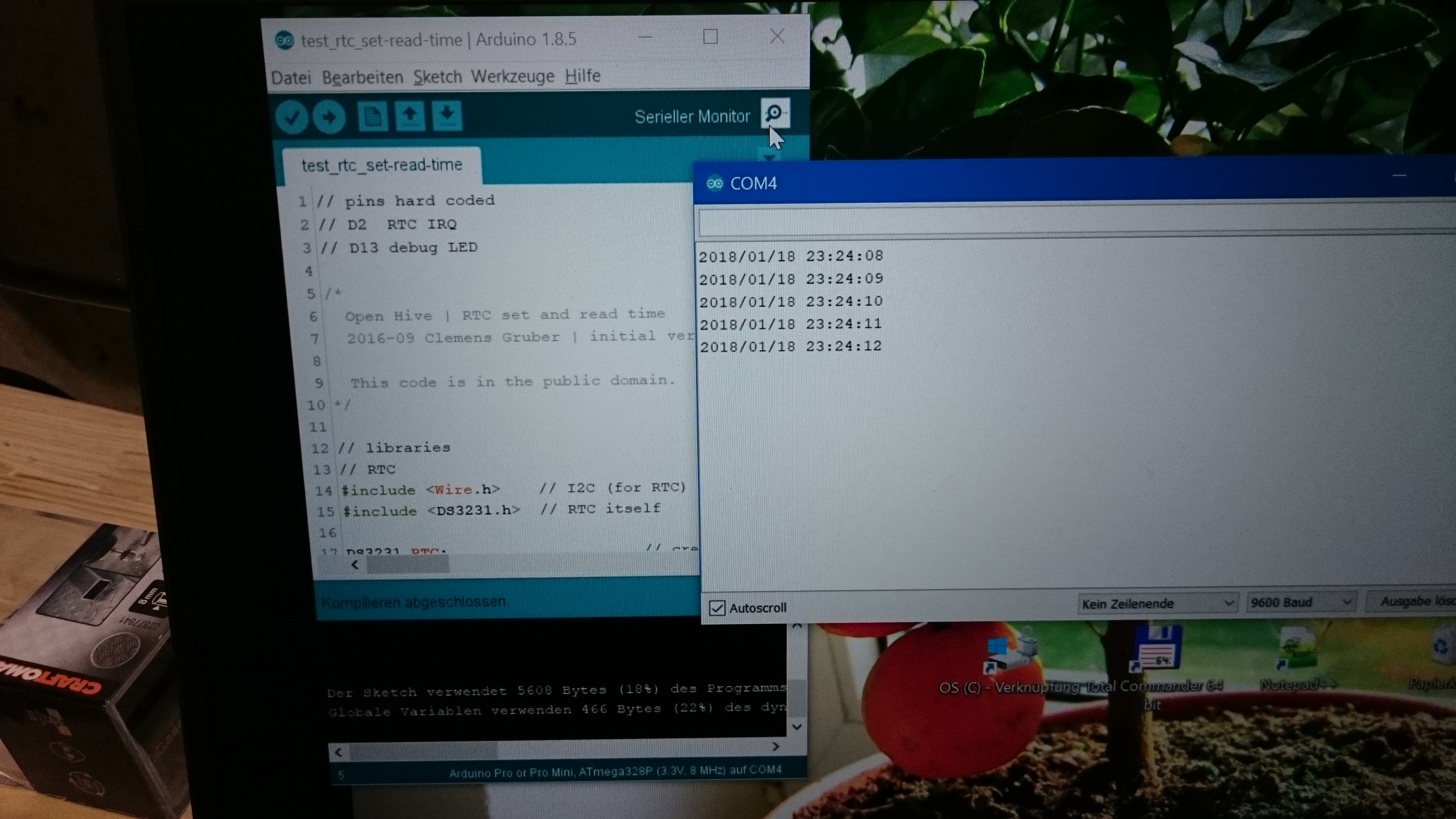
First step is to set the RTC time.
rtc_set-read-time.ino (1.1 KB)
The time on the board is set to the compiling time of the sketch. Every reset of the board will set the time back. So you should upload the set time sketch and following the next step immediatly.
… and Scale Adjusting
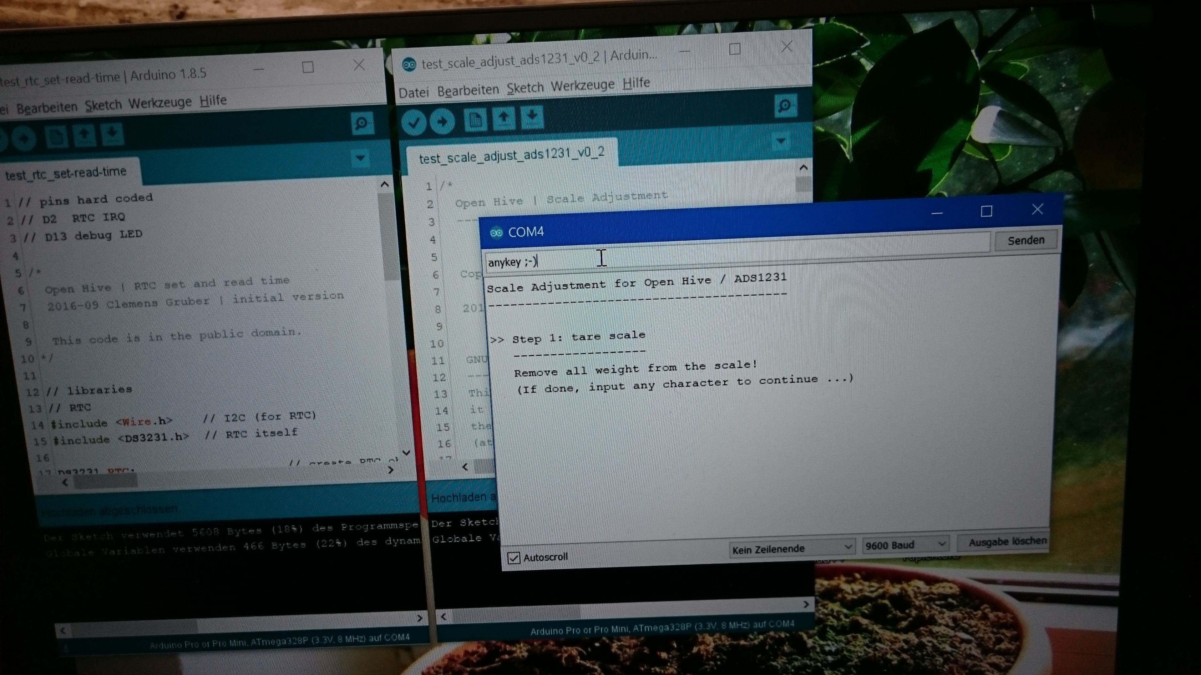
Upload the adjust scale sketch and start the serial monitor.
scale_adjust_ads1231_v0_2.ino (8.5 KB)
You will find there some step by step advices.
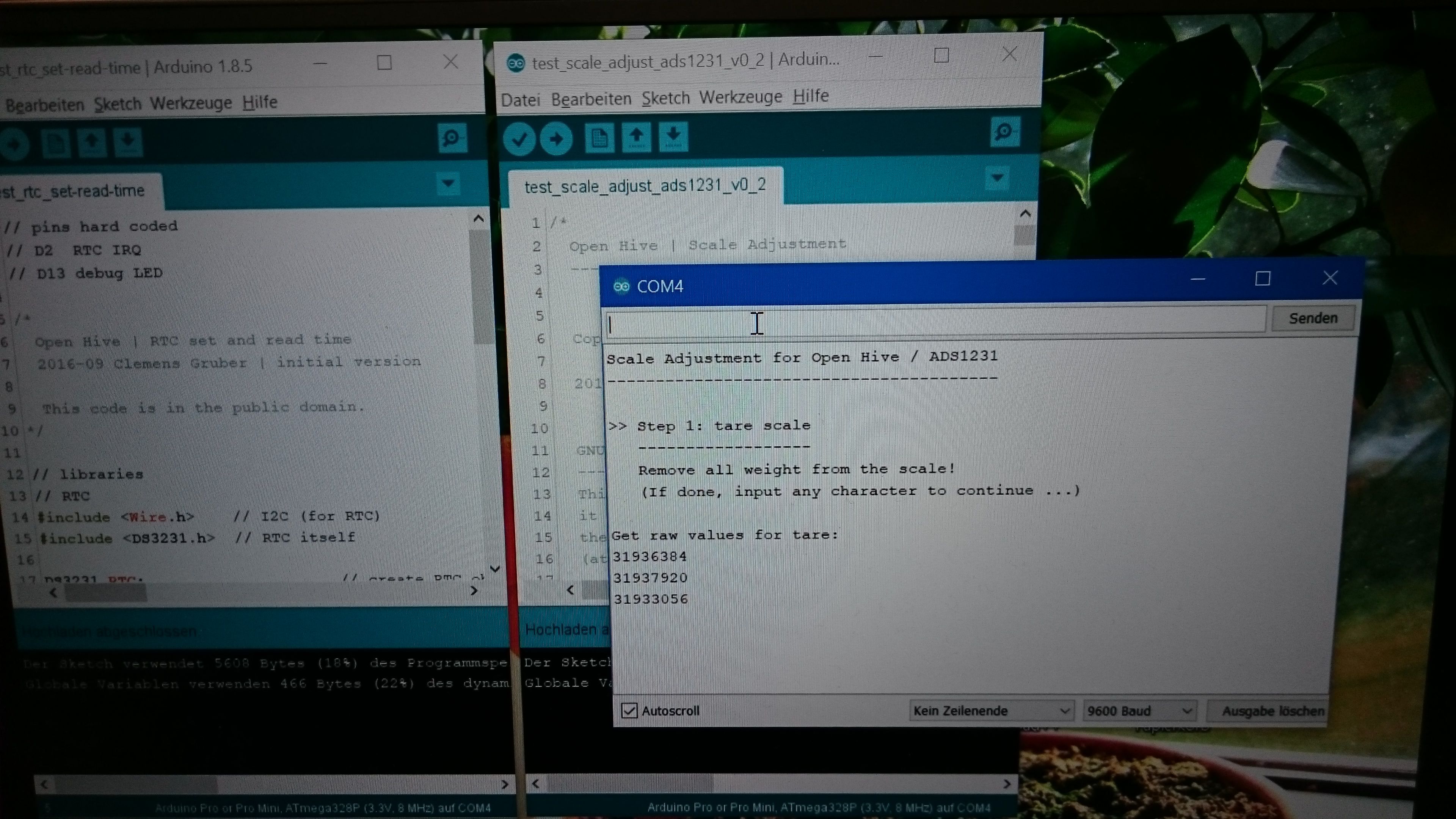
On the serial monitor you can see raw values of the load cell. For the adjustment you need some heavy goods. And you have to konw the weight!
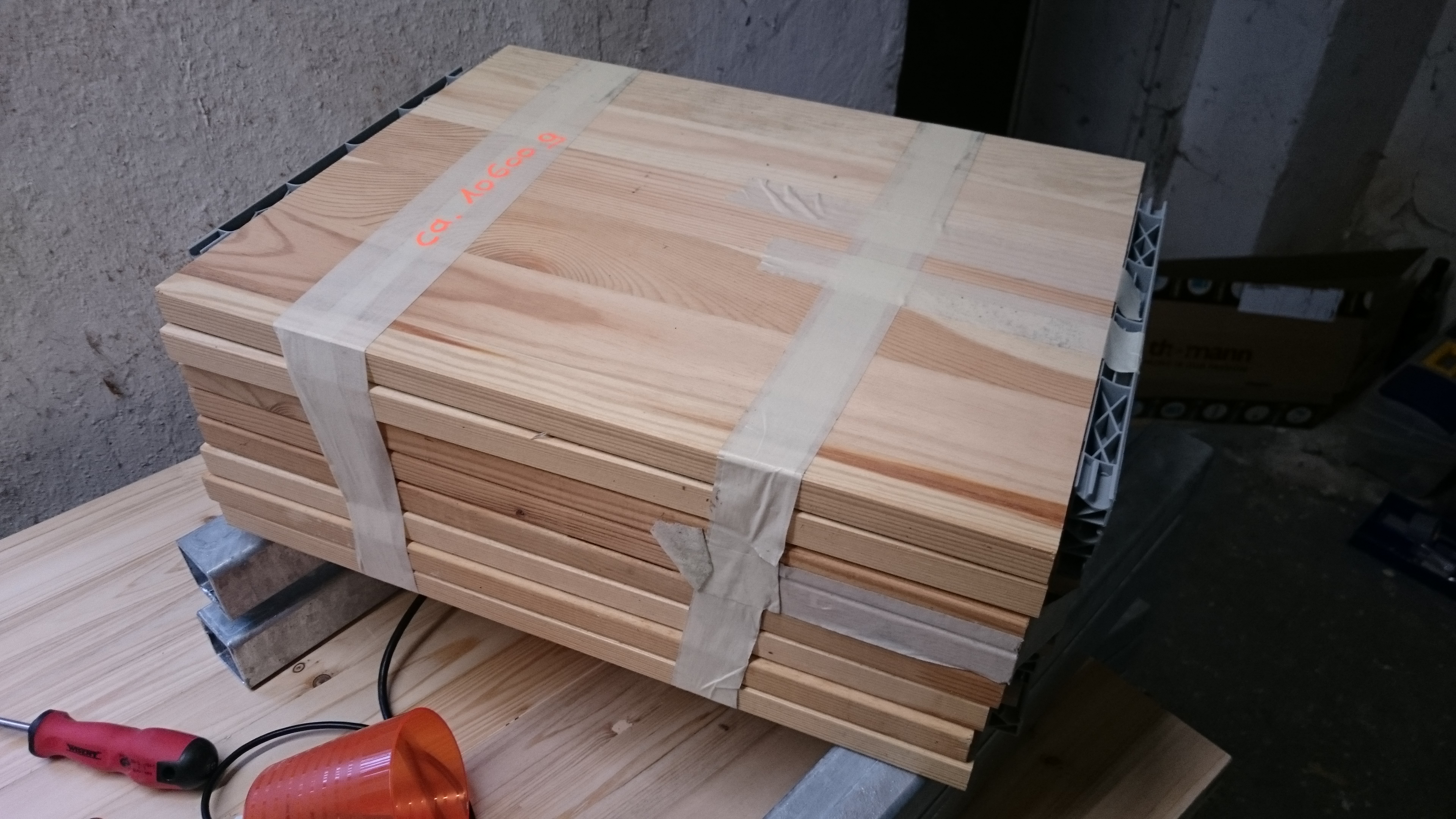
The scale frame with the calibration weight, in this case we have 10600 g.round about.

At the end of the adjustment you get two numbers for
LoadCellZeroOffset
LoadCellKgDivider
Download the main firmware sketch and copy&paste these values from the serial monitor into the source code:
- Current development head: node-gprs-http.ino
- Snapshot version 0.21: node-gsm-wifi_stalker31_v0_21.ino (35.0 KB)
Save the modified sketch with the added load cell parameters and …
… upload the sketch to the board. Software done!

Some documentation again. ;-)
(source: 正版新葡新京 - 官网 - 正版新葡新京)
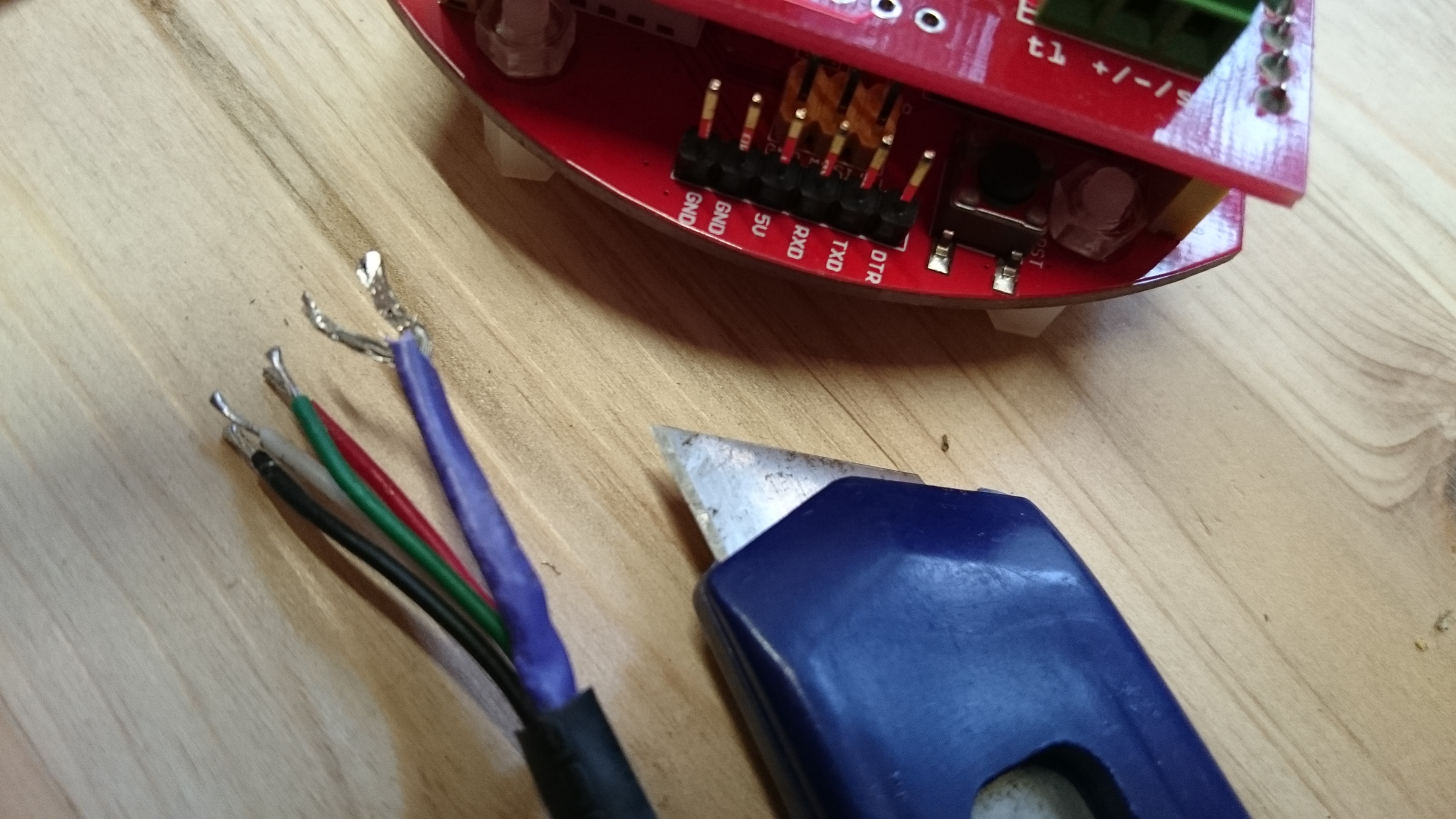
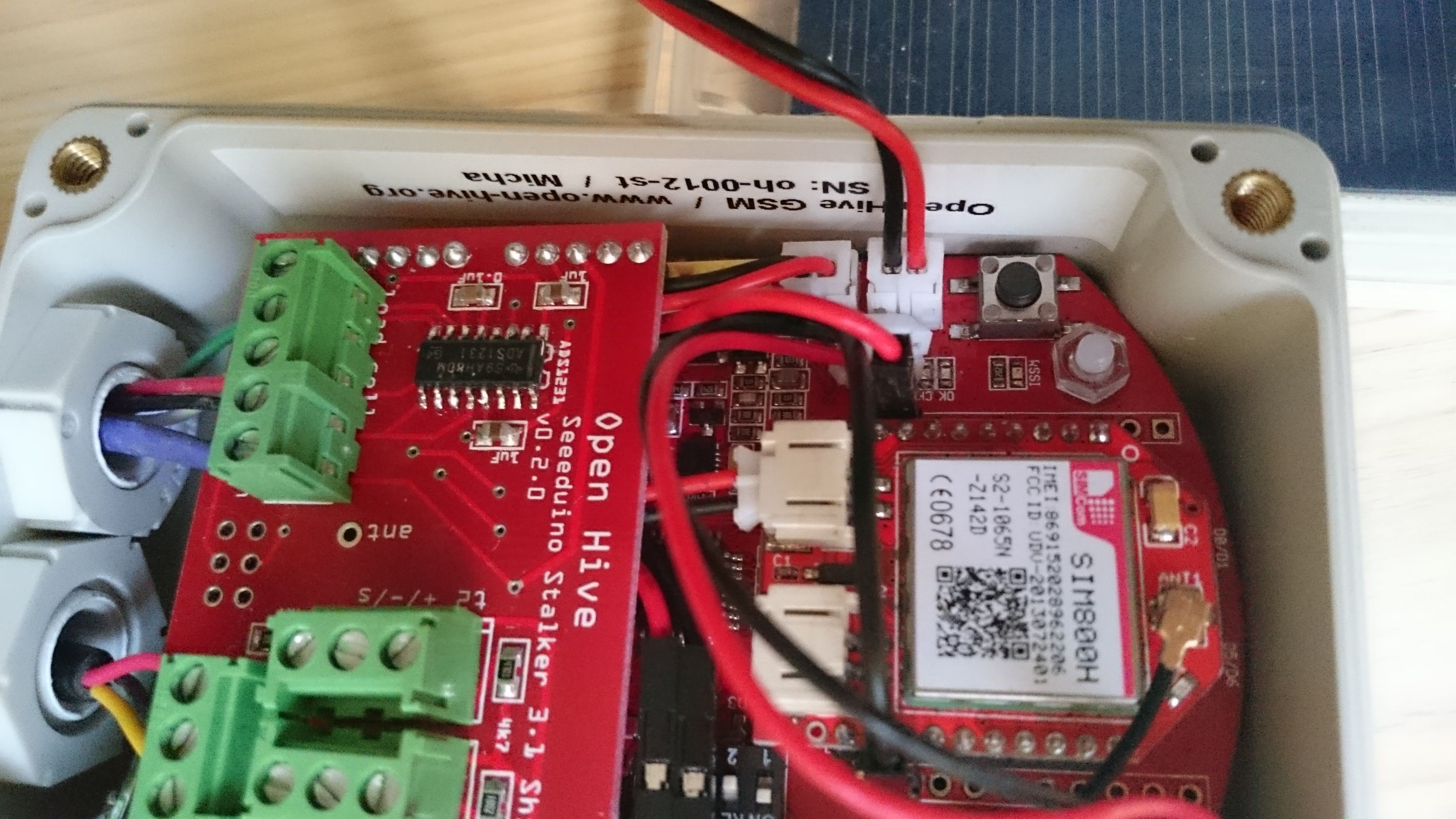
Two Flying Wires for the GPRSBee
This and the next two pictures show the connection between the GPRSbee and the board.
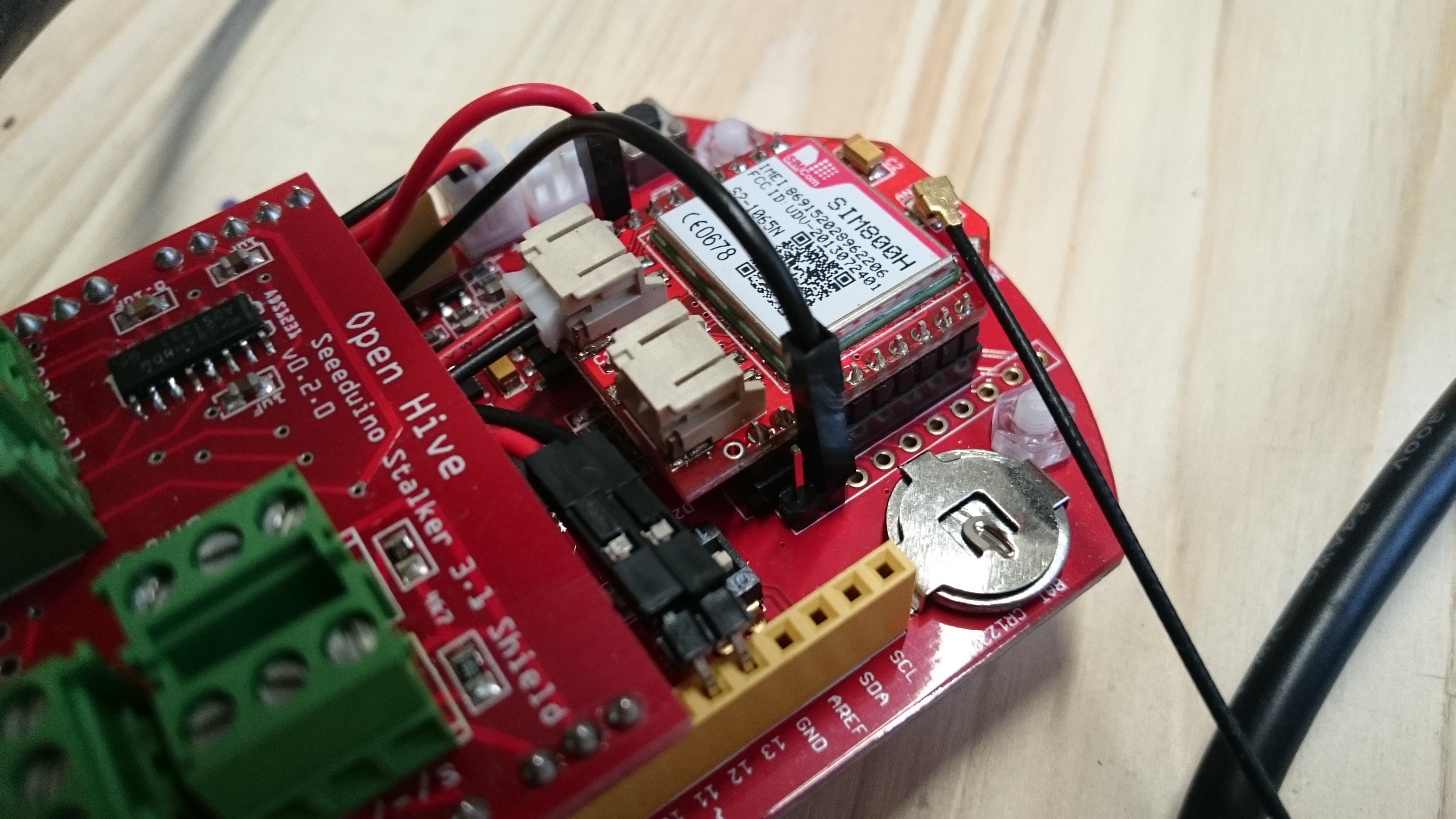
GPRSBee’s CTS pin is connected to Arduino’s pin 13, the black wire in the picture.
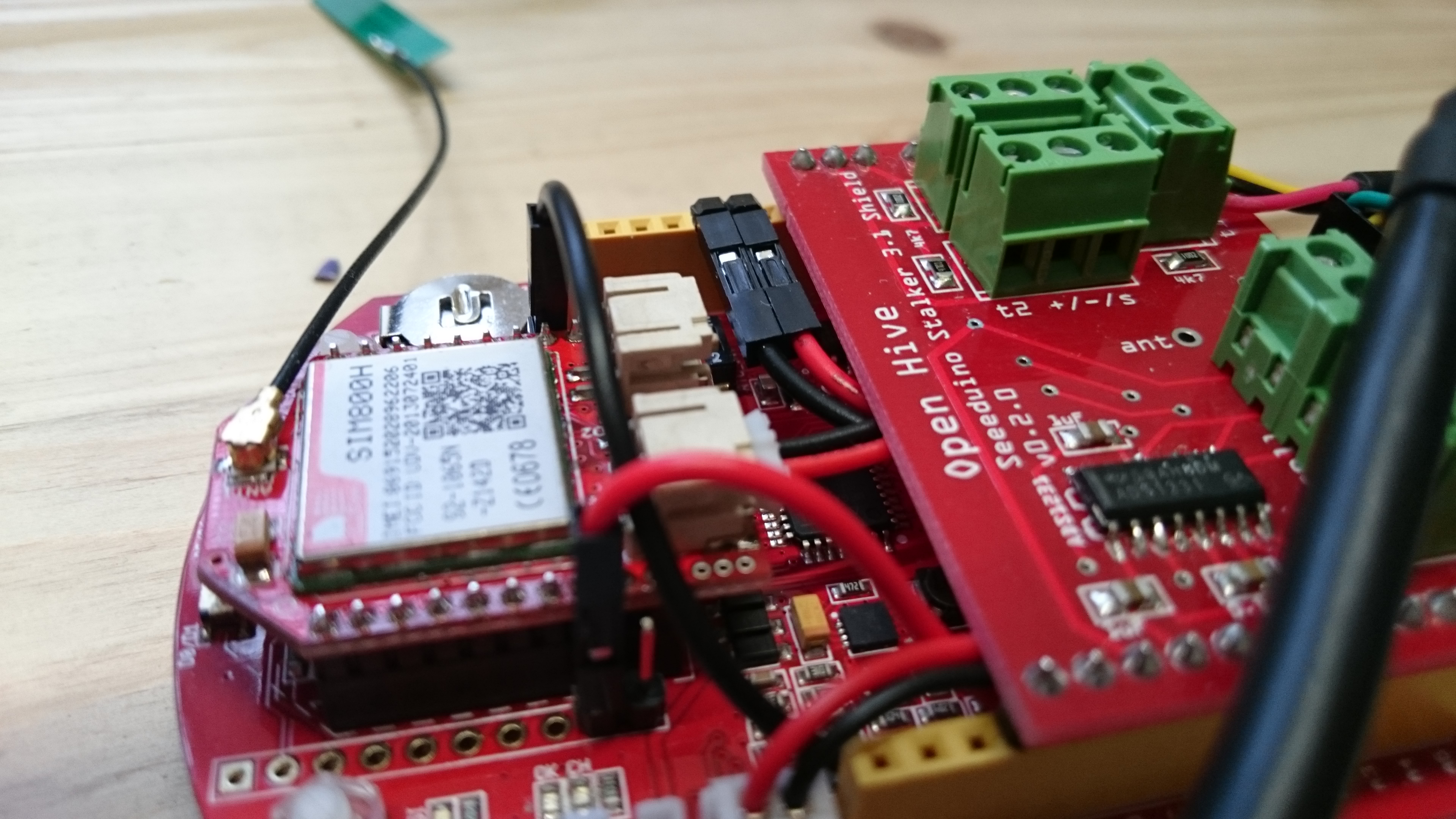
The DTR pin of the GPRSBee module is connected to Arduino’s pin 12, red wire
Insert the SIM card

Lift up the GPRSBee module and turn it upside down.
Pay attention to the sloped corner of the SIM card and …
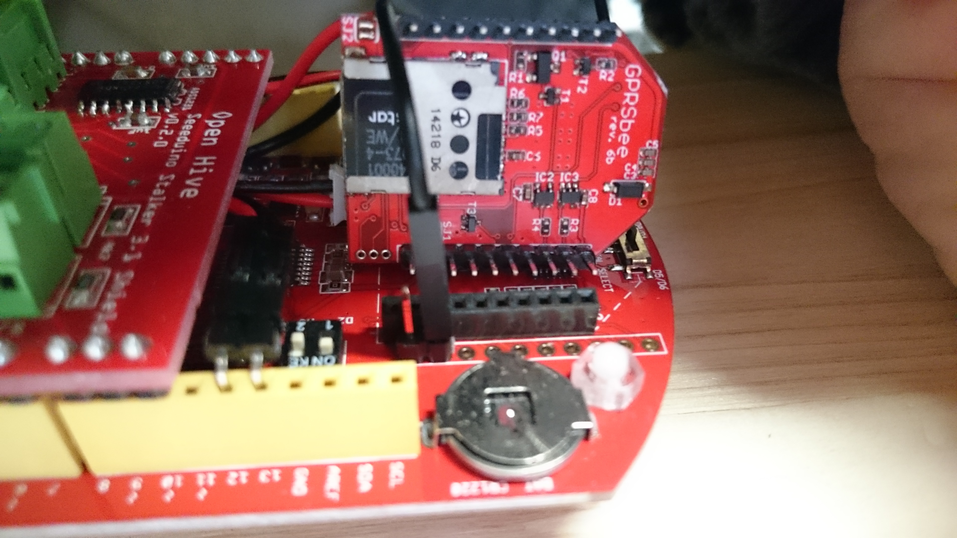
… insert the card gently in the slot.
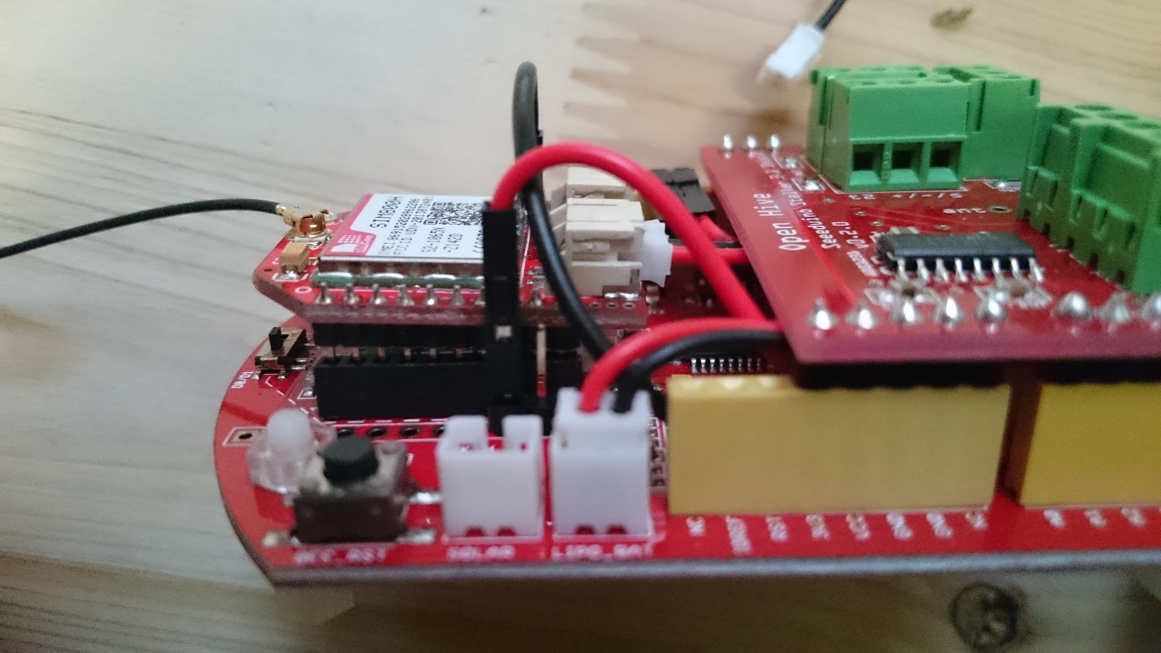
Insert the GPRS module back in the bee socket, pay attention that all pins are in the fitting socket. In the picture the bee is–for demonstartion purpose–not fully inserted. You can see the golden pins. In case the module is pushed fully in the socked you will not see them.

Insert the LiPo cable also. In the picture it is not fully put in (but for me better removable after testing :-). Best it should look like the second plug, cable from GPRSbee module to the board.
Real World Test
Great! SIM module (green LED) is blinking, good news!
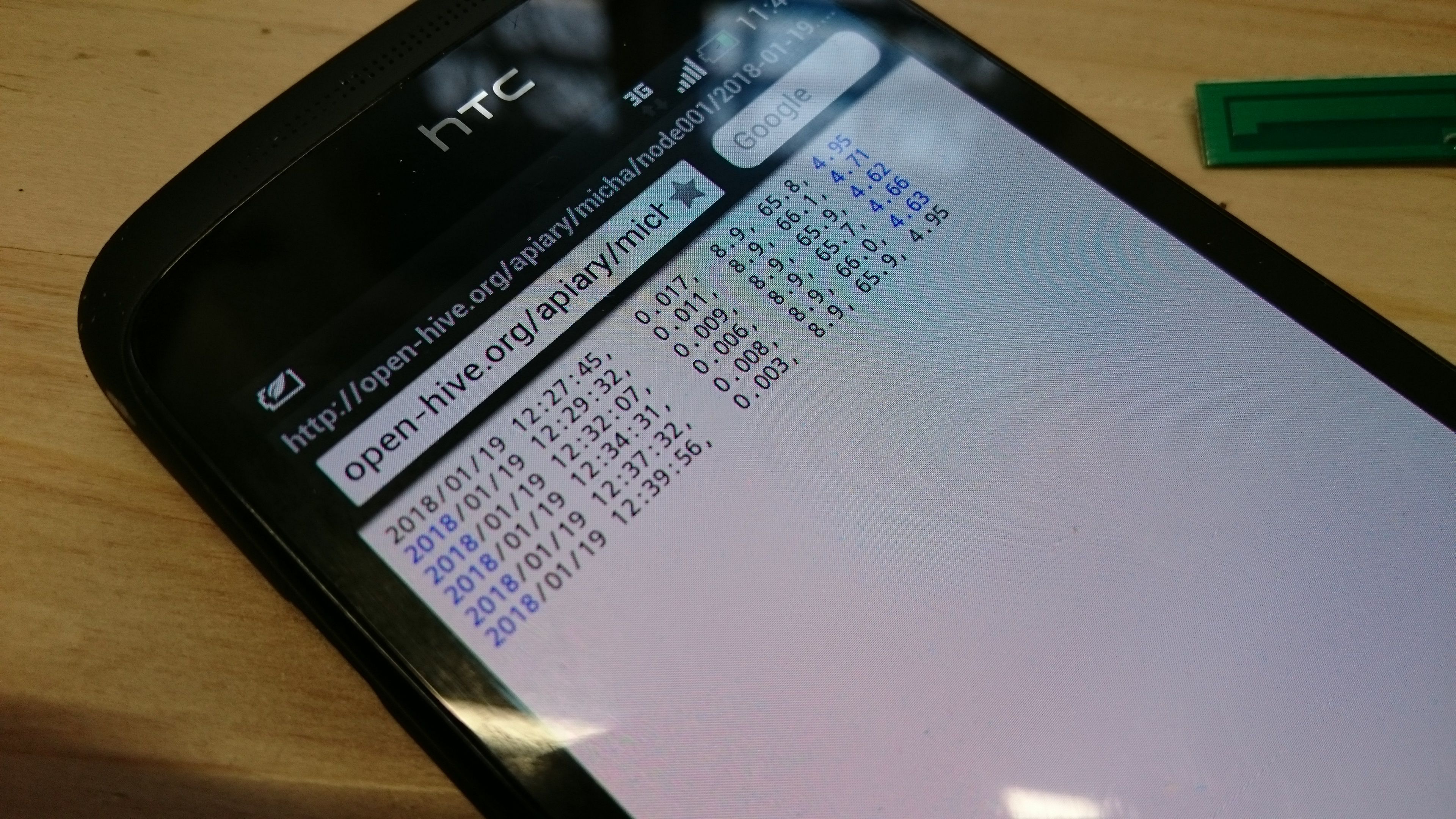
After blinking has stopped it should take some seconds and the sensor data reaching via GPRS / air – internet – server – internet back – WiFi or LTE (ok perhaps also GSM ;-) your mobile phone! Wow! What great technology!
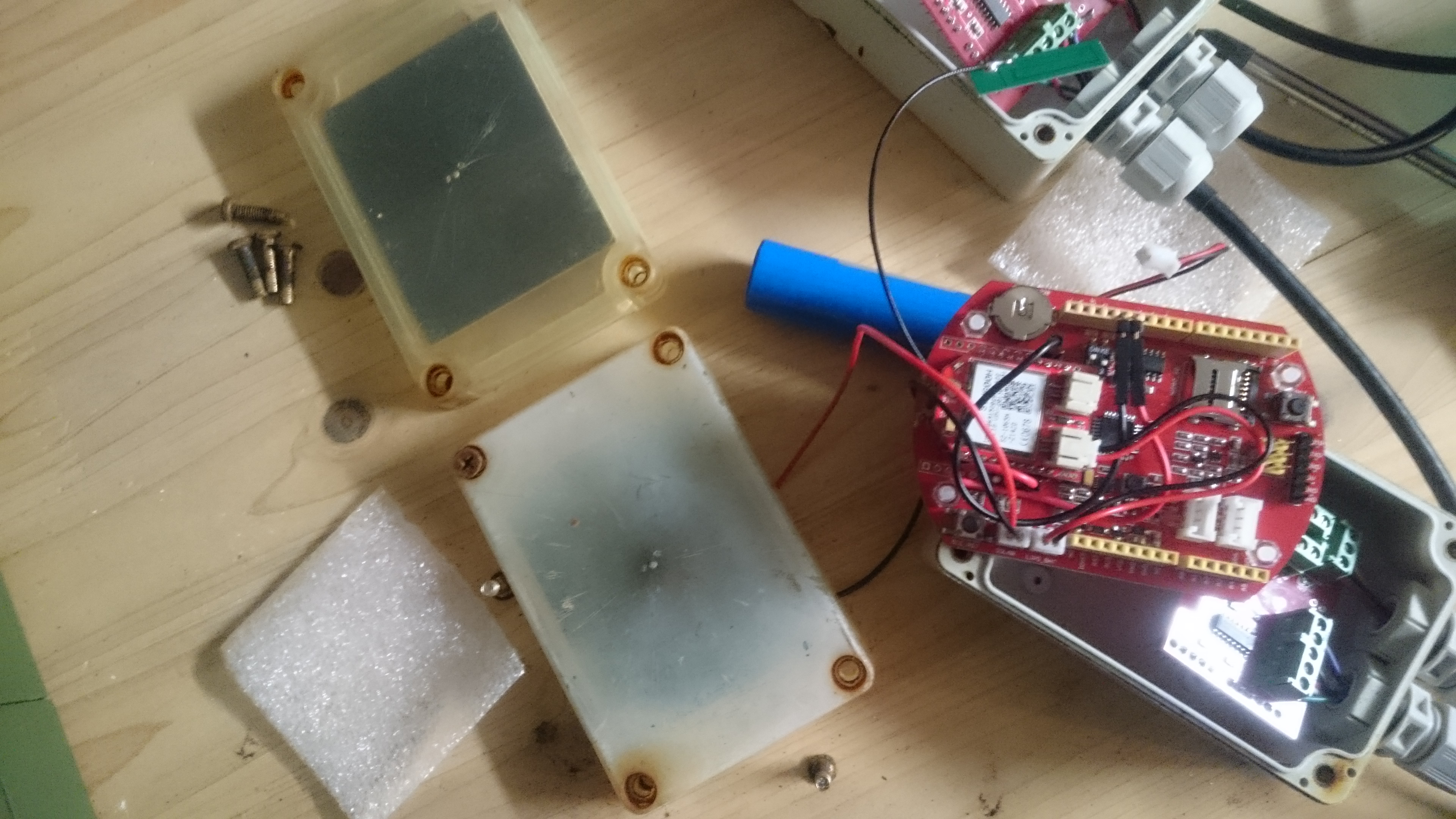
Putting all Parts in the Box
So things are working and we can put all parts in the case.
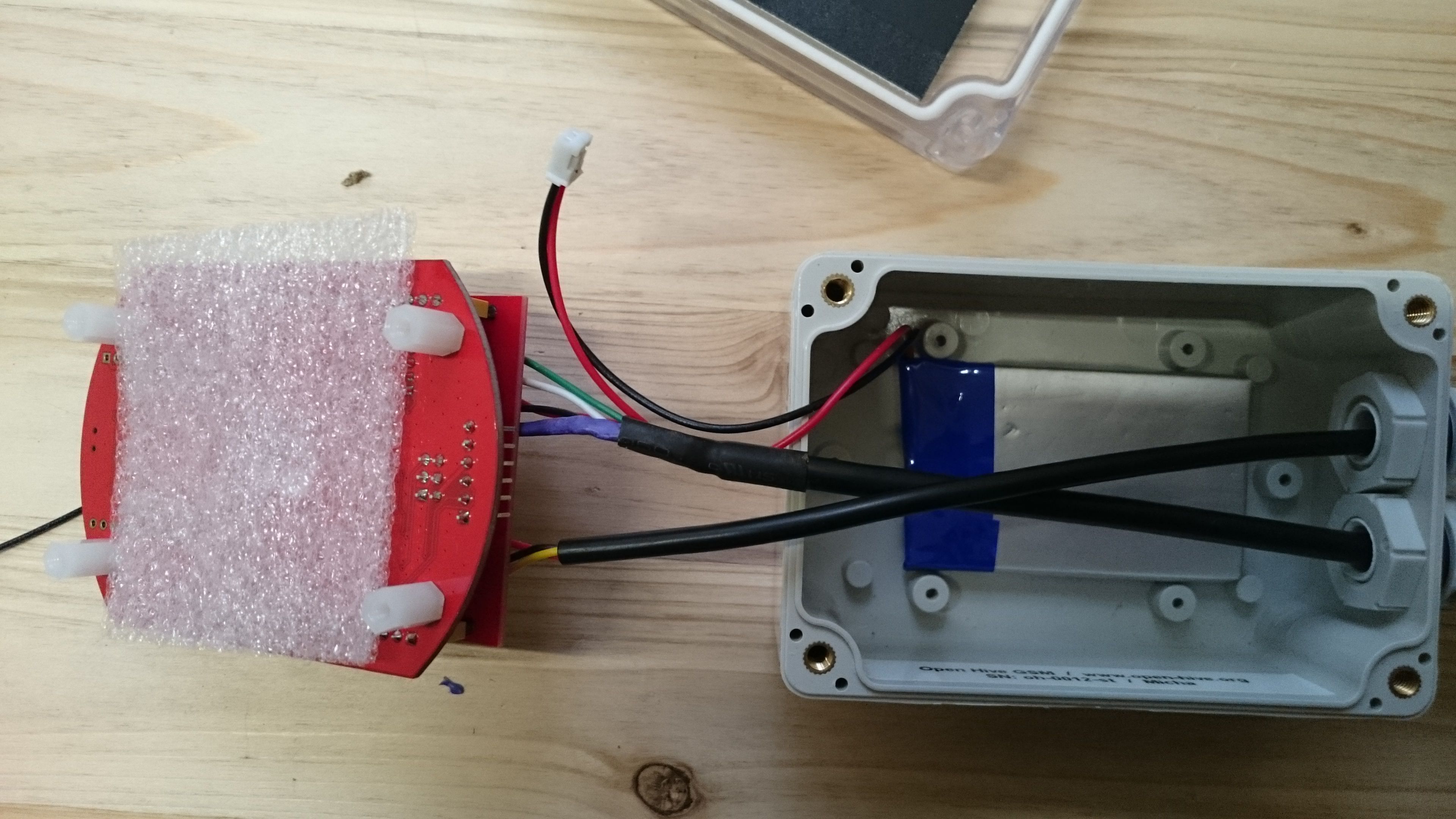
Put the LiPo in the case. Add a layer foam between LiPo and Seeeduino Stalker board so that the THT parts will not damage the battery.
Postion the board in the case and push the cables a bit in case they do not move gentle some time. Especially the fat load cell cable with the heat shrink tube needs sometimes a bit support.

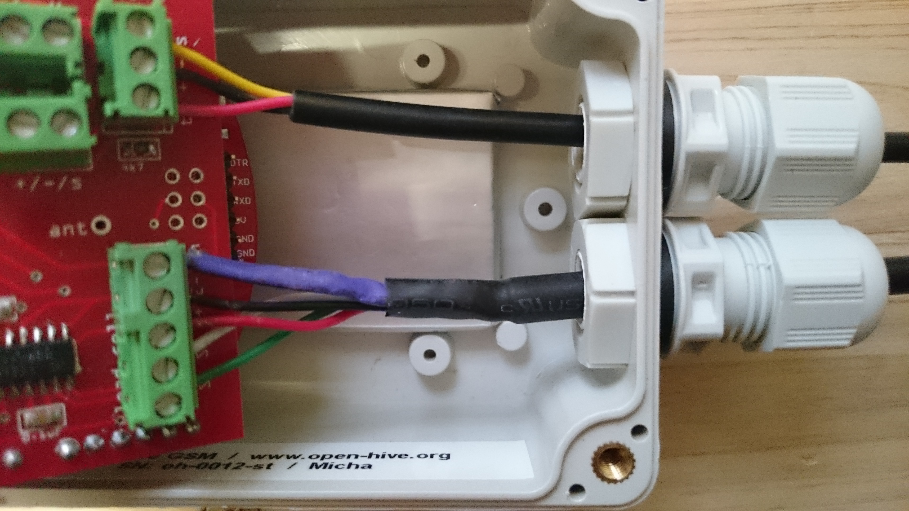
Put the antenna next the Seeeduion Stalker board.
Connect the solar cell with the main board.

To reduce humidity put a silica gel bag in the box.
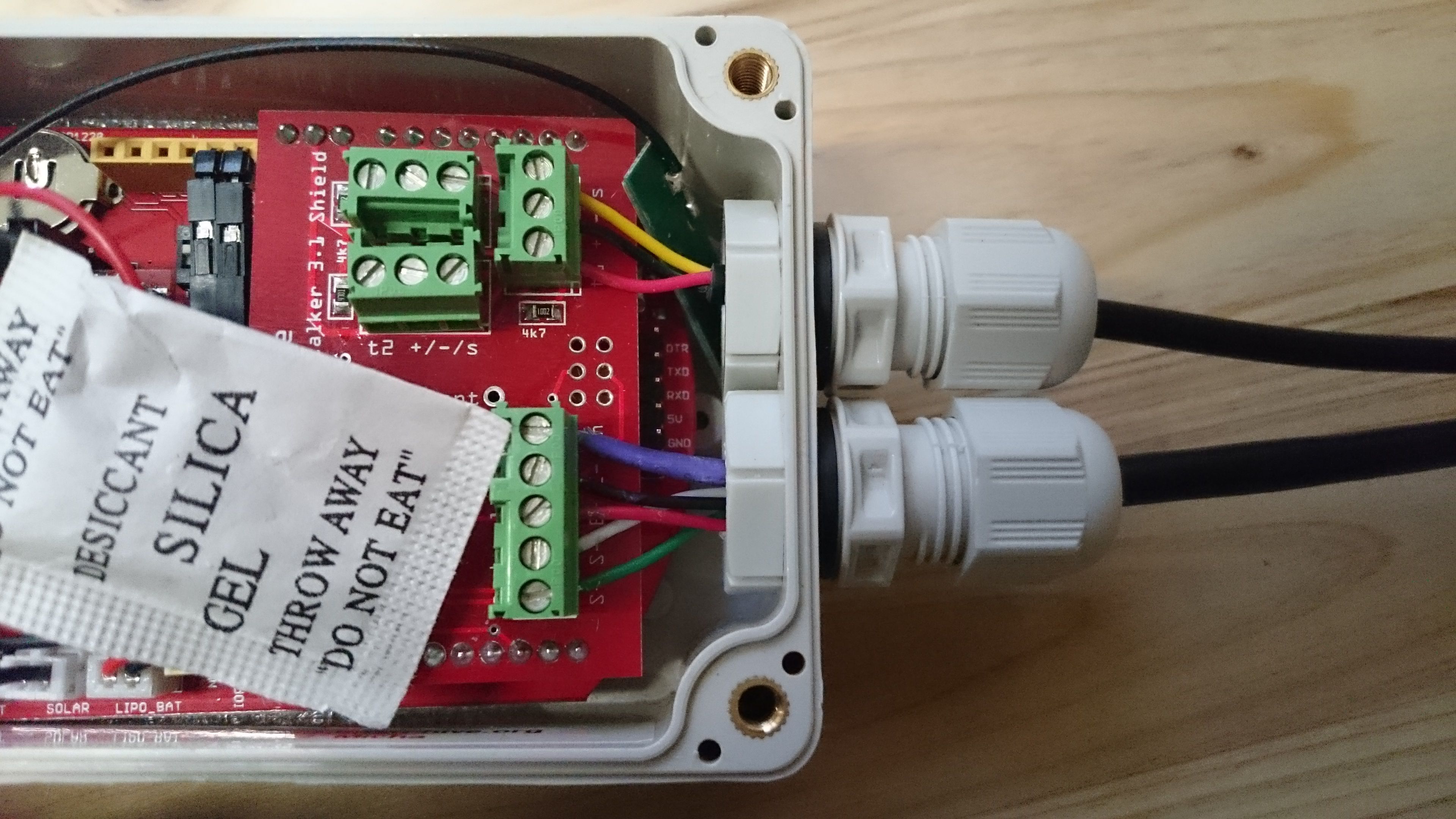
Tighten the cable glances. This will prevent the inner box from dust and water and reduce mechanical strain.

Tighten the four screws. First insert all screwas and thight it weak. After all screws got the screw thread tight them best in diagonal order.